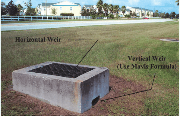
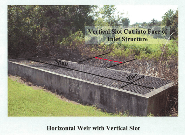
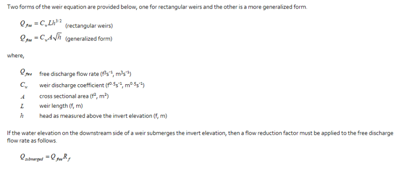
Eng-Tips is the largest engineering community on the Internet

Intelligent Work Forums for Engineering Professionals

horizontal weir equation

Replies continue below

Recommended for you

See below images for a rectangular horizontal weir. The other option is a circular horizontal weir.

Horizontal_Weir_vs_Vertical_weir_p1ihm8.png

Horizontal_Weir_vs_Vertical_weir_2_whv1x1.png

Horizontal_Weir_vs_Vertical_weir_3_lvxu4b.png

Horizontal_Weir_vs_Vertical_weir_4_eg9kc4.png


kckcei,

Sorry, I wasn't real clear on what I was trying to say. The situation you are dealing with is, as you initially referenced, what I would call an inlet rather than a weir. In this situation the inlet will behave like a weir until the water reaches a certain head level, then the inlet will act like an orifice. I think your software is trying to tell you this also. The equation I sent in the attachment is for the weir scenario, I would guess until the depth is about 1X to 1.5X the narrowest dimension of the inlet box before it starts to act like an orifice.
 
What I would normally do is treat the top of the inlet as four vertical weirs with end contractions up until the the flow rate starts to decrease instead of increase and then treat the opening area as an orifice. How about this approach? That works fine for square or rectangular inlets, but how do I calculate end contractions on a circular inlet? There is a circular stand pipe equation that can be used for that.

 
From ICPR 4 help:

Horizontal Weirs
A ditch bottom inlet is an example of a horizontal weir and behaves as a vertical sharp crested weir for lower heads, with the weir length equal to the perimeter of the inlet. As head builds up on the inlet, the opening can become overwhelmed at which point the opening behaves as an orifice, restricted by the opening area rather than the perimeter length.


icpr_weir_Capture_nwh2up.png
 
I think this is what I have been looking for:
Horizontal Weir Flow
For horizontal weirs, flow is first calculated as if the weir is vertical and rectangular, using the
perimeter of the weir as its length. Then a second calculation is made assuming orifice flow based
on the cross sectional area of the opening. ICPR then compares the two and takes the lesser value
as the controlling flow for the opening.

The only problem is that end contractions to not appear to be considered. If it is then maybe it is calculated using 2 end contractions since there is only one length.
And, for circular ditch bottom inlets the the same vertical weir equation is used with the perimeter being equal to the circumference. Is this correct?

 
KC,

I think what is going on in this situation is there are no end contractions for this condition since the rectangular drop inlet does not have side walls, essentially the weir width is the same width as the channel in which case there are no end contractions.

I would use the inside dimensions of the drop inlet for the weir length. This does make me wonder if the inside corners of the drop inlet impact the flow rate vs the same length of straight weir. I have not found any information related to this, likely negligible but one would think by now someone would have performed the experiment.

Thanks for your post. You have got me thinking about this type of work that I was fairly heavily involved in a couple decades ago in the Missouri Ozarks. I still have interest in stormwater but do not get opportunity to practice these days.

Good luck and please post if you find any additional info.

 
The flow over a horizontal weir is determined using the modified Francis formula:

q = 0.415 (L - 0.2 h.) ho^1.5 (2g)^1\2 Where: q = volumetric flow rate, ft / s L = height of crest, ft ho = height of fall of the weir.

There are no end contractions on a vertical inlet. The perimeter length of a vertical inlet is considered a horizontal weir.

The vertical inlet should be designed with adequate capacity so that there is never a transition to full pipe flow. That is how a glory hole vertical inlet is designed. If the vertical inlet doesn't have adequate capacity, the transition from less than full flow to full flow will be unstable and should be avoided. The transition may not be a problem with smaller pipes but will be a major problem with larger pipes.

glory_j6bw10.jpg


With full pipe flow out of a submerged inlet, the inlet losses are typically considered to be minor losses compared to the full pipe flow headloss.
 
bimr,

Great picture!

Where is ho measured?

In a submerged inlet like the one in your picture at what point does anti vortex need to be considered? Do you have any formulas or rules of thubm for anti-vortex protection?

Thanks
AKSherpa
 
The Bureau of Reclamation has designed several of these for some of the dams near you. Doesn't appear they have anti-vortex protection. Maybe you can visit one?

"The Glory Hole"

The video states that the shaft makes a hard 90[sup]0[/sup] turn at the bottom.

 
Interesting, thanks for the article. I imagine with a hole that size it doesnt build up enough depth to vortex.

I am in Alaska, I don't think we have any of these up here butr maybe I can go visit on my way thru the northwest someday.
AKSherpa
 
Back
Top