Eng-Tips is the largest engineering community on the Internet

Intelligent Work Forums for Engineering Professionals

How can a frame have a single element to represent its overall stiffness? 1

Status
Not open for further replies.

Julian2w2w

Mechanical
Jun 2, 2020
17
0
0
MU
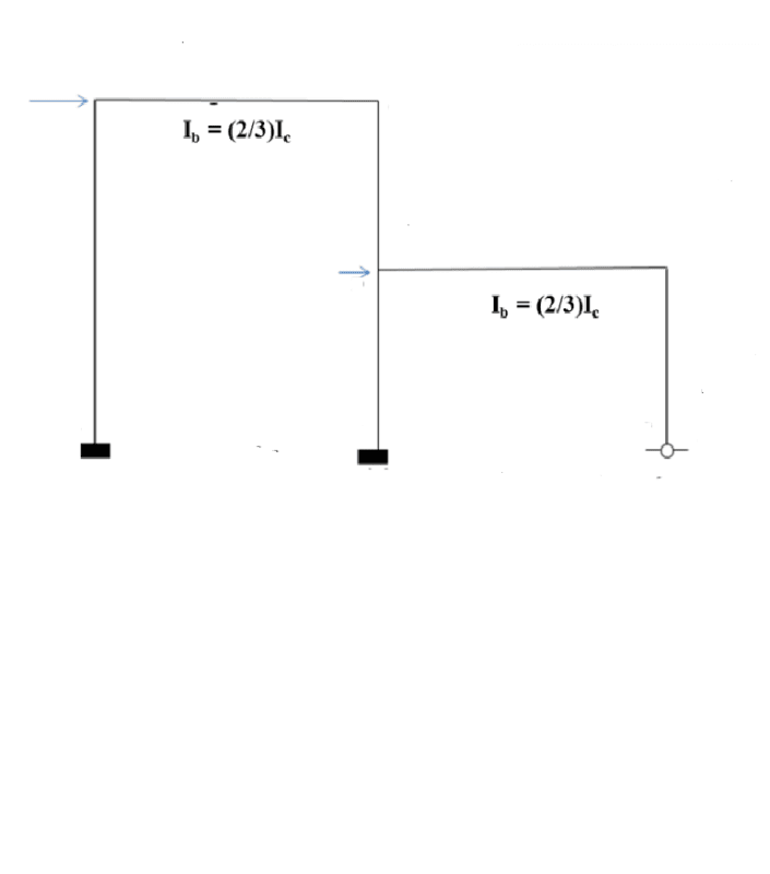
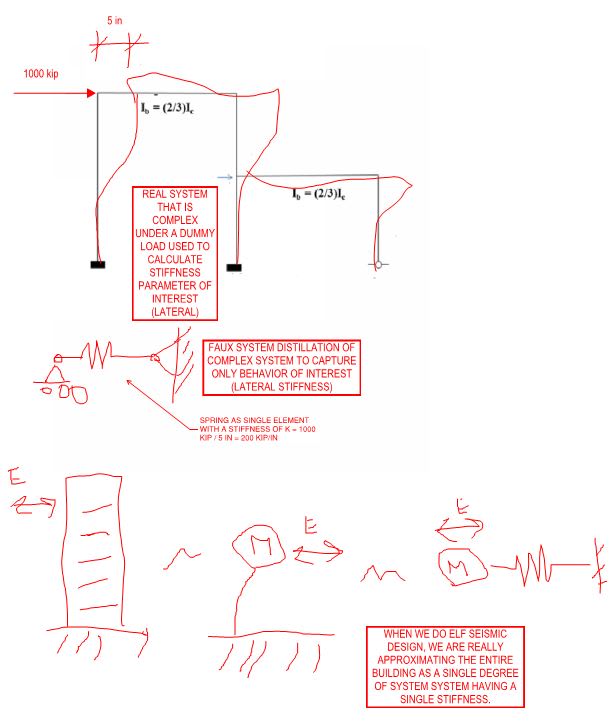
Hox can a frame have a single element to represent its overall stiffness?

I found that in a book. From what I remember, a single-storey or double or multi-storey have a matrix of stiffness.

Only a structural member can have one element to represent its stiffnees?
 
Replies continue below

Recommended for you

The size of stiffness matrix depends on number degree of freedom.
So if a frame stiffness is a single value, I think DOF is lateral displacement.
 
Ahaa, that makes sense, so only the element of the matrix concerned with that displacement will be considered and the rest of the elements disregarded?
 
I saw a frame on the web, kinda corresponding to what you are saying, in terms of a single degree.

So you mean the frame below can have a single value for representing its stiffness, so what expression would you get for a single value from that system?

If you say so, then for that 2-storey 'SDOF' system, the beam has to be considered axially rigid, so that only the column stiffnesses are considered, else it would be immpossible.

Untitled_ipdnyh.png
 
The figure you post has 2 DOF. And yes, generally if we want to focus on lateral displacement, we assume beam is rigid body. Otherwise the K matrix will be more complicated, due to the consideration of DOFs from beam.
I'm not sure if my comprehension of this part is correct or not.
Hope someone can give out a better and clearer explanation.
 
No worries, it makes sense for the beam to be assumed to be axially rigid.

But then what would be the single expression for its stiffness, I personally think it should be a 2 x 2 stiffness matrix
 
Yes, the figure has 2 lateral disp. need to be considered. So DOF should be 2, which makes K a 2x2 matrix.
If a system has number degree of freedom = N, the size of K matrix would be NxN.
 
I am sure even though it is a 2-storey, the stiffness matrix can not be :
2k and - k in the first row and
- k and k in the second row?

Plus there is a pin support at one end

What will be the elements in the stiffness matrix?

Can somebody help here please? Thank you
 
the figure has 2 degrees of freedom for lateral sway, but has another 5 degrees of freedom for joint rotation bringing the total degrees of freedom to 7. So to do a stiffness analysis would require a 7X7 stiffness matrix.
 
We were talking about lateral swway only arising from let's say a seismic load, and beams and columns axially rigid.

So what you would get, write your stifness marrtix row by row and let's see!
 
you've got 2 fixed supports and one pinned, yes?

the left and central verticals are beam columns, the right vertical is a column only.

This can be a 2D problem or 3D.

I don't get the "Ib = 2/3*Ic" comment, but maybe that's something you structures people know ?

You can assume the members are axially rigid or elastic.

another day in paradise, or is paradise one day closer ?
 
If the beams and columns are axially rigid (as distinct from flexurally rigid)the degrees of freedom of the structures are 7x7.
If the members are not axially rigid the degrees of the structure are 9x9
 
"How can a frame have a single element to represent its overall stiffness?"

a beam element has many degrees of freedom (one element does not mean one degree of freedom).
A beam element models axial stiffness, shear stiffness, bending stiffness about two axes, torsion.

another day in paradise, or is paradise one day closer ?
 
This is difficult to answer without knowing the context in which you're seeing references to single element models. My best guess is shown below.

c01_e2y0md.jpg
 
KootK from your diagram the structures has 13 degrees of freedom taking in account axial and flexural displacements. The structure stiffness would be a 13 x 13 matrix and this would represent the structure stiffness in its most general form (if I correctly recall my frame analysis lectures 30 years ago).
 
civeng80 is correct on DOF for general purpose frame analysis, as 3(DOF)/node*4nodes +1 rotational freedom of the rightmost column. However, it is another matter for seismic/dynamic analysis. The linked article discuss the basic. Link
 
civeng80 said:
KootK from your diagram the structures has 13 degrees of freedom taking in account axial and flexural displacements. The structure stiffness would be a 13 x 13 matrix and this would represent the structure stiffness in its most general form (if I correctly recall my frame analysis lectures 30 years ago).

retired13 said:
iveng80 is correct on DOF for general purpose frame analysis, as 3(DOF)/node*4nodes +1 rotational freedom of the rightmost column. However, it is another matter for seismic/dynamic analysis. The linked article discuss the basic. Link

I'm afraid that you guys have not picked up what I intended to lay down. Hence the lessons in entry level static indeterminacy. Let's try it this way:

1) I could take the frame, introduce a zillion nodes into each beam and column, and have a zillion elements and a zillion degrees of freedom. A matrix the size of the universe at 8pt font & single spacing.

2) By the same token, I could also condense all of degrees of freedom associated with all nodes and members into a single degree of freedom of my choice as I did above.

3) Again by the same token, I could condense the degrees of freedom to three, nine, seventeen, eighty one, or four. Whatever.

The number of DOF for analysis is a matter of choice. The designer chooses based on the resolution they wish to see in the output.
 
civeng80 said:
KootK from your diagram the structures has 13 degrees of freedom taking in account axial and flexural displacements. The structure stiffness would be a 13 x 13 matrix and this would represent the structure stiffness in its most general form (if I correctly recall my frame analysis lectures 30 years ago).

KootK didn't comment on the number of degrees of freedom in the complete frame. It is true that for a standard 2D analysis the frame would have 13 degrees of freedom, or 9 (not 7) if axial strain and vertical deflections are ignored, but if you are only interested in the horizontal displacement of the top of the structure under horizontal loading it can be reduced to a 1 degree of freedom system, as shown in Kootk's diagrams.

Doug Jenkins
Interactive Design Services
 
Status
Not open for further replies.
Back
Top