5H4D0W
Mechanical
- Mar 29, 2018
- 19
I am trying to generate some documents (pdf) from my drawing sheets in NX.
I want to use primarily A4 and A3 size sheets. ISO / NS Standard.
Firstly, the generated dimensions, symbols, and annotations, are oversized. Well, the 3.5 size of the dimension text is actually within ISO standard specs, but would be preferable at 2,5. Annotations such as view labels, SCALE, etc. are all too big. I also tried adding a point to the model to signify the center of gravity, and noticed that this too comes up too big. Sketch points made in the drafting application have the same symptom.
Secondly, when exporting pdf-documents, the lines of the drawing become oversized. So much that it hides several features, such as threads (see attachments). The only way around this, is creating a pdf though the print function, which allows me to scale the lines in the drawing by a given factor. In my example, a factor of 0.5 gives good results. (Annotations/text/dimension/symbols still a problem)
Now, my theory is that these issues arise because the standard settings of the drafting application is intended for larger drawings. These line thicknesses and font sizes work better on A0 documents. I have seen engineers make their document A0, and then print it as an A3. This isn’t really going to help, because it ruins the given scale of the drawing, effectively pushing the problem further down the line. I actually have Technician/machinist friends who have complained about improper scaling on NX-based drawings (not mine). Is this a “global” phenomenon?
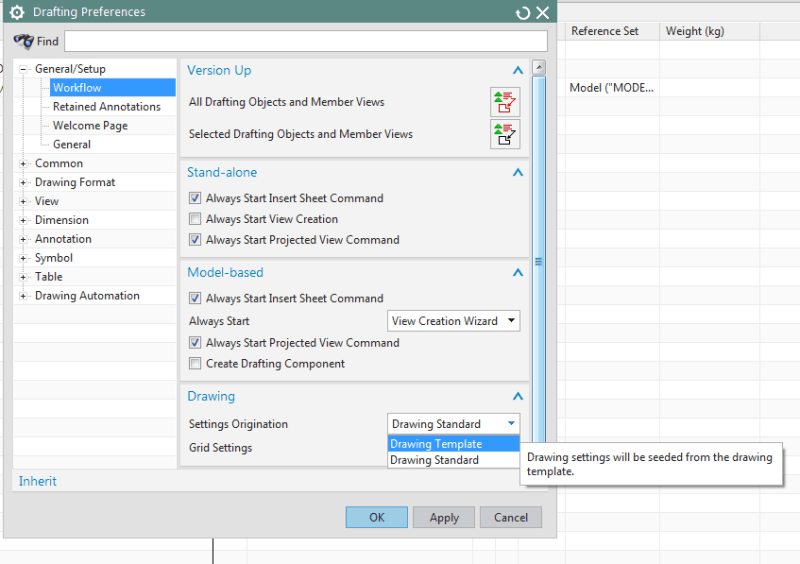
In conclusion, I want to know if the drafting application has been set to large formats, can I change it, or do I literally have to create a whole new ISO-based standard in the Customer Defaults? (I have tried this, but it doesn’t give me the opportunity to change all widths. I also do not find controls for whatever is upscaling the widths in the export pdf function. There are additional elements of the drafting environment that I wish to change, that either are not present as options in the customer defaults / drafting standards, or are simply too difficult to find due to the inherent complexity of it all).
Any help on this would be greatly appreciated.![[smile] [smile] [smile]](/data/assets/smilies/smile.gif)
Attachments [Note: some text in Norwegian, Please ignore]:
[URL unfurl="true"]https://files.engineering.com/getfile.aspx?folder=f557fc40-0968-44c8-8a5e-2ba67f790d77&file=test17_(via_print).pdf[/url]
[link ][/url]
I want to use primarily A4 and A3 size sheets. ISO / NS Standard.
Firstly, the generated dimensions, symbols, and annotations, are oversized. Well, the 3.5 size of the dimension text is actually within ISO standard specs, but would be preferable at 2,5. Annotations such as view labels, SCALE, etc. are all too big. I also tried adding a point to the model to signify the center of gravity, and noticed that this too comes up too big. Sketch points made in the drafting application have the same symptom.
Secondly, when exporting pdf-documents, the lines of the drawing become oversized. So much that it hides several features, such as threads (see attachments). The only way around this, is creating a pdf though the print function, which allows me to scale the lines in the drawing by a given factor. In my example, a factor of 0.5 gives good results. (Annotations/text/dimension/symbols still a problem)
Now, my theory is that these issues arise because the standard settings of the drafting application is intended for larger drawings. These line thicknesses and font sizes work better on A0 documents. I have seen engineers make their document A0, and then print it as an A3. This isn’t really going to help, because it ruins the given scale of the drawing, effectively pushing the problem further down the line. I actually have Technician/machinist friends who have complained about improper scaling on NX-based drawings (not mine). Is this a “global” phenomenon?
In conclusion, I want to know if the drafting application has been set to large formats, can I change it, or do I literally have to create a whole new ISO-based standard in the Customer Defaults? (I have tried this, but it doesn’t give me the opportunity to change all widths. I also do not find controls for whatever is upscaling the widths in the export pdf function. There are additional elements of the drafting environment that I wish to change, that either are not present as options in the customer defaults / drafting standards, or are simply too difficult to find due to the inherent complexity of it all).
Any help on this would be greatly appreciated.
![[smile] [smile] [smile]](/data/assets/smilies/smile.gif)
Attachments [Note: some text in Norwegian, Please ignore]:
[URL unfurl="true"]https://files.engineering.com/getfile.aspx?folder=f557fc40-0968-44c8-8a5e-2ba67f790d77&file=test17_(via_print).pdf[/url]
[link ][/url]

