Eng-Tips is the largest engineering community on the Internet

Intelligent Work Forums for Engineering Professionals

  • Congratulations waross on being selected by the Tek-Tips community for having the most helpful posts in the forums last week. Way to Go!

How do I represent a magnetic reed switch in a circuit drawing? 1

Status
Not open for further replies.

HaZakated

Mechanical
Jun 13, 2006
10
Hello All,

SITUATION:

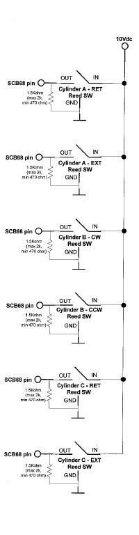
I am a beginning mechanical engineer analyzing a DC circuit. This circuit's purpose is to monitor the activity of a piece of testing equipment.
The best drawing that we have of this circuit at this time is shown below:

circuit.jpg


PROBLEM:

The monitoring computer is not recieving a signal from the switch that controls Cylinder A-EXT. We analyzed the entire circuit along with replacing the reed switch three times with no success. We also tried replacing the resistors with potentiometers to adjust the resistance with no success.

QUESTION:

I have a circuit CAD program called TINA PRO. How should I draw this circuit such that I can run it and troubleshoot it from a theoretical standpoint. Basically, I wouldn't have the slightest clue how to tanslate the drawing above to the circuit design program.


Thank you for your time.

Brian

 
Replies continue below

Recommended for you

A reed switch either closes or it doesn't. That doesn't mean that your computer will see it when it happens. Is the switch position not at an end position that would give a stationary ON? It may be that the switch closure is only momentary as it passes the magnet and inbetween the computers scan. There are methods to add a capacitor to increase the effective length of a pulse. Most often these will require an addition of a transistor or IC. This is where black box design meets reality.
 
Does the computer see the signal if you place a shorting jumper across the reed switch in question? If not then maybe that channel of the NI DAQ card no longer works.

And are you sure the program monitoring that channel is written properly?

It could also be a problem with the magnet that is supposed to actuate the reed switch.


~~~~~~~~~~~~~~~~~~~~~~~~~~~~~~~~~~
"It's the questions that drive us"
~~~~~~~~~~~~~~~~~~~~~~~~~~~~~~~~~~

 
After replacing the potentiometer (within the CYL A-EXT parallel branch)with a 9.5k Ohm resistor (which is much more resistance than thought to be needed), the system is working correctly. The rest of the resistors are 1.5k Ohms.

Does anyone have any idea as to why this much resistance would allow the computer to recieve the signal correctly?
 
What model is the DAQ card that is connected to the SCB-68? I assume it is made by National Instruments.

Most NI DAQ cards only accept 0-5V TTL inputs- I see that you are supplying 10V- could be a major issue with potential for failures. But really need to know the model #.

~~~~~~~~~~~~~~~~~~~~~~~~~~~~~~~~~~
"It's the questions that drive us"
~~~~~~~~~~~~~~~~~~~~~~~~~~~~~~~~~~

 
I do not know who designed the circuit, but I would strongly suggest dropping the 10V to 5V. Looks like the 6229 is for TTL compatible signals 0-5V. Don't know what the absolute max rating is but you are probably close to the failure margin. Here is a link to the manuals


~~~~~~~~~~~~~~~~~~~~~~~~~~~~~~~~~~
"It's the questions that drive us"
~~~~~~~~~~~~~~~~~~~~~~~~~~~~~~~~~~
 
I believe the reed switch used in this circuit needs 10 volts to operate.

We are thinking of applying a voltage divider after the switch. Any other ideas?


In my experience a reed switch does not require any power to operate it's contacts. Contact actuation is provided by the magnet's absence or presence.

A voltage divider approach should work though.

Good Luck

-AK2DM

~~~~~~~~~~~~~~~~~~~~~~~~~~~~~~~~~~
"It's the questions that drive us"
~~~~~~~~~~~~~~~~~~~~~~~~~~~~~~~~~~

 
HaZaketed, you never said whether or not the magnet passing the reed switch was a momentary thing or not. If it is, then it sounds like the stray capacitance of the input might be stretching the pulse for you. When the reed switch closes, the signal goes high. When the reed switch opens, the signal will go low with an RC time constant. A higher resistance would take longer to go low. I wouldn't want to count on stray capacitance as being a reliable way to stretch a pulse. But, before you address this, you really do need to fix the circuit so that it doesn't destroy your inputs with overvoltage.
 
Status
Not open for further replies.
Back
Top