Eng-Tips is the largest engineering community on the Internet

Intelligent Work Forums for Engineering Professionals

How to calculate the EMF in a circuit with 2 opposing batteries? 2

Status
Not open for further replies.

Total Novice

Electrical
Mar 8, 2023
12
0
0
AU
EDIT:
Just realised now I didn't post the actual question. So sorry everyone.
The question says "What is the resultant EMF in the circuit?"

Hello,

I am not an electrical engineering student/engineer, but I have a related question I was hoping someone could help answer.
Here is a picture of the question:
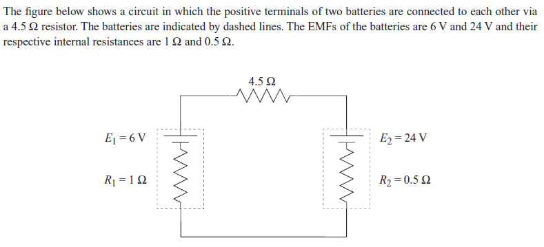
Purple_circuit_10_scxix3.jpg


This is not homework.

I would like to know, the formula for EMF (from what I have found online) is e = V + Ir where e = the electromotive force, V is the volts, I is the current, and r is the internal circuit. But the answer for this is simply "24 - 6 = 18", and the explanation for this is that the batteries's positive terminals are facing the each other so the voltage is working against each other, and the 24V one is going to over power the 6V one. That is all logical even if you don't have any electrical circuit knowledge, but what I don't understand is what happened to the e = V + Ir formula? Why was this not used at all? People who were discussing this question also said that if the batteries were facing the same way, the EMF would simply be 24 + 6 = 30. Again, the formula is not used. Is the EMF simply a sum of the 2 battery's voltages?

Thank you in advance.
 
Replies continue below

Recommended for you

It's helpful to know where you found this; it's possible it makes sense, but it's also possible the explanation there is in error.

However the simplest explanation is that at any point in the circuit one can calculate the voltage relative to some other point in the circuit the EMF between those two points.

Typically some point is chosen as 0V, which is arbitrary. This circuit could be hanging on a wire that is 10,000V attached to the connection between the two batteries, but the change in EMF would be the same around the circuit.

Pick a direction, such as counter-clockwise, and call that the positive direction. Start at the connection between the cells. Going to the top of the 24V cell is considered +24V; going the other way the +6V in the negative direction is -6V, so the difference in EMF between the tops of the cells is 24V+(-6V) or 18V.

Likewise if you start at the top of the 24V battery and go in the negative direction you see -(-24V) + -(6V) which again is 18V.

Had you been given the 24V and a current though the resistor then you would see +24V - I*4.5 Ohms to see the EMF at the top of the other battery.

See
 
Regarding where I got this question from (@3DDave), this is a standalone question in a GAMSAT practise booklet. This exam and their practise booklets are, if I must say so myself, notorious for very badly worded questions and answers that are more about corrupting the wording of the question and/or answers in order to trick and confuse candidates, than providing a fair and clear objective question to test candidates, so there is no context to speak of or to base this question on, and there is no way for me to know if I am supposed to do something or not, to get to this answer.

These question booklets have answers but do not come with explanations about their answers so "suggested answers" are simply what other people have worked out and posted video tutorials of online and people discuss ways to get the answers in the comments.

Sometimes the questions allow you to make real world assumptions, sometimes you are not allowed, but they never tell you when, and the only way you know is by "cheating" and checking the answer key first, then you will know what you were supposed to have done to get the "right" answer. And that is the only context I can provide unfortunately.

So, since the answer is 18, I know it is because they wanted you to do 24 - 6, but my question is, why do it this way when the formula is e = V + Ir? 24 - 6 written as a formula seems to be V2 - V1, which is NOT the same formula as e = V + Ir.

I had a look at the Khan academy link you posted about Kirchhoff's Law. Admittedly, I have not had the chance to look deeply into this yet, but, is that related to the formula e = V + Ir?
 
The more typical presentation of such a problem usually requires you to calculate the actual voltage somewhere in the loop, say across the right side battery.

You would then create a loop equation +24V -I*R2 - I*R1 -6V -I*R3 = 0 and solve for I, which would then allow you to use 24V -I*R1 to solve for the actual voltage across the battery. The sign of the current will get corrected by the loop equation solution.

TTFN (ta ta for now)
I can do absolutely anything. I'm an expert! faq731-376 forum1529 Entire Forum list
 
The voltage is the directed sum of the voltages.
+24 Volts plus -6 Volts = 18 Volts.
You have an EMF of 18 Volts driving current through (0.5 Ohm + 1 Ohm + 4.5 Ohm) = 6 Ohms, 3 Amps.
The 6 Volt battery will be charging.
I have encountered this circuit in Central American Lobster boats.
The engines were 24 Volt, start and charge.
The electronics were 12 Volts, fed from a 12 Volt battery.
The load was 12 Volt engine room lights. (In place of your example's 4.5 Ohm load.)
The lights were always on in the engine room and the 12 Volt battery for the electronics was kept charged.
Question for your instructor;
"Were would we see this circuit in the field?"
Suggestion:
"Would this work?"


--------------------
Ohm's law
Not just a good idea;
It's the LAW!
 
If EMF is calculating the terminal voltage of the battery then first calculate the current in the circuit then use that current to calculate the terminal voltage.

Be careful of battery polarity and current polarity when you add voltages together. One battery will have less than it's ideal voltage at it's terminals, the other more voltage than it's ideal voltage.

It's just a series circuit, pick your convention for current flow direction and start calculating the current and voltage across each component. Again, watch the polarity...
 
EMF versus terminal voltage.
As I use the terms, EMF is the force available to drive the current, or the open circuit voltage.
Terminal voltage is the actual voltage under load.
Thus EMF minus internal voltage drop equals terminal voltage.
A rigorous solution is surprisingly difficult.
Consider, at 3 Amps, the internal voltage drop in the 24 Volt battery is 1.5 Volts and the terminal voltage is 22.5 Volts.
With 22.5 Volts the current will be slightly less. A true solution may be moving out of the realm of simple arithmetic.
But, battery actual voltage seldom equals terminal voltage depending on the state of charge.
When the voltages are given as nominal voltages, it is common to neglect the effect of internal voltage drop on the current or to consider only the first iteration of the reduced voltage.
One last important factor: The IR drop across the 6 Volt battery will be a voltage rise rather than a voltage drop.

--------------------
Ohm's law
Not just a good idea;
It's the LAW!
 
Thanks everyone, as I said, I don't know anything about electrical engineering so there are a lot of terms I don't know, like what terminal voltage is.

To answer Waross' question :
Question for your instructor;
"Were would we see this circuit in the field?"

and
"Would this work?"

These questions are not done in a classroom, it is from a practise booklet created by the examiners. You do the questions yourself and there is no guidance on what why the correct answer is what it is, so there is no one to ask. As such, I don't even know if this circuit would work in real life or if you would ever have a circuit like this, the only thing I recognised was that it might be charging since both positive terminals are pointed towards each other. Whether the 24V battery is charging the 6 volt one (like a powerbank) or whether they are both contributing to the charging of a device (with resistance 4.5 Ohm) connected to it, I have no idea. "Would this work?" - I would imagine this could be say a toy or electrical device that is being charged simultaneously by 2 batteries? Like a bucket being filled simultaneously by 2 water sources pouring into the same bucket?

I tried some calculations based on what Lionel has suggested. I know that voltage in series is additive, so you can just add all of the voltages. Since we don't know the total voltage, but we do know that the total voltage subtracted from itself is 0, we can do what IRStuff said, which is to subtract all of the voltages and make them equal to zero.
So what I did was, starting at the 24 V battery and going counter clockwise for current flow, I said the negative terminal to positive terminal direction is positive current flow, but then since we are subtracting, I reversed the signs. Since voltage is equal to I*R, I did:

I*R2 - 24V - 4.5*I - (6V - 1*I) = 0
I*R2 - I*4.5 - 6 + I*R1 - 24V = 0
I*R2 - I*4.5 + I*R1 - 6V - 24V = 0
and R2 = 0.5, R1 = 1
then
I(0.5 - 4.5 +1) - 6V - 24V = 0
I(0.5 - 4.5 +1) - 18V = 0
I(0.5 - 4.5 +1) = 18V
I(-3) = 18V
I = 18V/-3
= -6 amps?
(and 6v -I*1 is negative and in their own brackets because it is its own battery and the current flows in the opposite direction for them, from the positive to the negative terminal).
This is slightly different to waross' suggestion in that I used negative 24 whereas waross used positive 24, (+24V -I*R2 - I*R1 -6V -I*R3 = 0 and solve for I). Not sure why 24 is positive here while everything else is negative?

Regardless, do I now use current = -6 in the e = V + Ir formula? r = internal resistance so it is 0.5 and 1, for a total of 1.5, but we still don't have V for the overall circuit. If Voltage is current x internal resistance, and current is -6 and internal internal resistance is 1 + 0.5 + 4.5 = 6, then is the voltage -6*6 = -36V? What about the 4.5Ohms?

This question is supposed to be done in around 1.5 minutes and the formula way seems to be too much effort for what its worth, and even if -36V is correct, how do I get the answer of "18V" from -36V?

Then I saw a definition of EMF (on a tutoring site, so not sure how reliable it is): "Emf is the voltage developed between two terminals of a battery or source, in the absence of electric current." and another one "EMF is the potential difference measured across a power source without a load connected to it".

For the first definition, we don't know if there is a current or not. Maybe it is not switched on, or the battery, despite being connected, is flat so there is no current. The second definition could have explained why the answer to this question is simply 24V-6V but there IS a load connected to it, it has a resistance of 4.5Ohms, so I still don't know why it is as simple as 24-6.
 
Wouldn't it be easiest to subtract 6 Volts from the circuit making it an 18V circuit with 3 resistors in series? Then just add the 6V back to whatever got calculated.
 
If the goal is to "get the number 18", then it is easier to subtract 6V from 24 to give 18V.

My question is how do I know that is what I am supposed to do, since, it asks for the EMF and when searching for EMF calculations, I am told to use the e = V + Ir which to me, bears no resemblance to "24 - 6 = 18", plus I will have to find I first.
 
It's algebra.

The usual convention places the positive supply voltage to the left and calculates clockwise - swapping the two

+24V - i*4.5 -6V -i*1 -i*.5 = 0
+24-6V -i*(4.5+1+.5) = 0
18V = i*6.

Or, by inspection of the circuit, realize you'll be subtracting the 6V eventually, so do it up front and add the resistances.

+18V = i*6.
 
@3DDave
Okay thank you, I understand this equation and thanks for telling me about the convention.

But my other question remains, which is why use this equation: This calculation gives us the voltage. If the question were asking for the total voltage or even the current, I suppose then this is how I could go about doing it. But the question is asking for EMF. So, does that mean EMF is the same thing as voltage? I didn't think they were the same. As I mentioned I looked up some definitions of them and neither of the understandable definitions were helpful. According to one definition, EMF is the same as voltage when there is no load on the current but there is a load here and it has the resistance of 4.5 Ohms.
 
EMF is the unloaded voltage and is taken as a constant. Normally that constant is used when a resistor is put in series with a battery to calculate the internal resistance of the battery, but that resistance is given.

So the question here is what is the unloaded battery voltage for each cell.

That will be the measured voltage plus the voltage drop / gain due to the internal resistance.

The confusion is that batteries are designed for open circuit voltages of 6 and 24 volts so it makes the question look like those are the open circuit voltages. With that much internal resistance (crappy batteries at best). I can't recall a need to find EMF this way - it's just easily measured. Typically engineers are concerned with voltage drop due to internal resistance.

By way of comparison a car battery may be as low as 0.022 Ohms. Most are less than 1 Ohm.

In this case the 24 V battery has an open circuit voltage higher than 24 because of the internal resistance is dragging it down and the 6 V has an open circuit voltage lower than 6 Volts because the internal resistance is pushing it up.
 
Thank you 3DDave for the explanations. Unfortunately my confusions have not been fully cleared yet so I am going to leave this for awhile and maybe come back to it later. But if you or anyone has nothing better to do... then here are a few more of my questions.

"EMF is the unloaded voltage and is taken as a constant ... So the question here is what is the unloaded battery voltage for each cell."
What is "unloaded voltage"? I looked up "unloaded voltage" and all the results talk about "voltage dividers" and of course I have no idea what that is. To help me, I would like to refer for a moment to the definitions of EMF I found online:
"Emf is the voltage developed between two terminals of a battery or source, in the absence of electric current."
and
"EMF is the potential difference measured across a power source without a load connected to it".
To me these bold words mean a circuit that is not using any power or does not have any devices connected to it, for example a circuit with a light bulb that is switched off. In the diagram, the light bulb would be the 4.5 Ohm resistor. If the light bulb is switched off, then there would be no resistance. The fact that the resistance is stated as 4.5 Ohms means it must be on or having a circuit pass through it.

Is the "unloaded voltage" for each cell, the voltage that the battery has, if it isn't powering anything? I think of load as a burden so an unloaded voltage or "unloaded battery voltage" sounds like a battery connected to a device but the device is not used so no current is flowing. Like a battery in a remote control that is not being used. (I also looked up "unloaded battery voltage" and the results were all about flat batteries).

"That will be the measured voltage plus the voltage drop / gain due to the internal resistance."
Just want to make sure I understand this: The "measured voltage" is the 6V and the 24 V and the voltage drop or gain would be due to R1 and R2, so the unloaded battery voltage for each cell is calculated as "6V + I*1" and "24 + I*0.5". Doing it this way means we don't know the value for current I at the moment, so we also don't know the exact values for "the unloaded battery voltage for each cell". But suppose at this point we calculated the the unloaded battery voltage for each cell. How does that get the EMF?
 
Just realised I didn't actually post actual wording of the question itself. Edited my first post to include the question now. So sorry everyone.
 
I*R2 - I*4.5 - 6 + I*R1 - 24V = 0

You didn't watch the signs. Draw the current loop clockwise or counterclockwise. I'd go counter-clockwise myself and it appears you started that way. Either can work as a starting point. Follow the loop around and put a + sign on the correct end of each component. Then add or subtract the voltage of each device to sum to zero.

Another way to handle this is to re-draw it with all the components in a straight vertical line so the components being in a loop don't mess with you getting the signs right.
 
EMF stands for electro-motive force, and as such, is a arcane term, since voltage is not a force, i.e., kg*m/s^2. "Electro-motive" is an allusion to something that causes electricity to flow; EMF is something I might have seen in textbooks when I was in high school. I think more plausibly, the internal battery voltage would be called "open-circuit voltage" which is typically what you see on a datasheet for a battery

In any case, each battery has an "EMF" which is the voltage shown next to the battery. If there is no current, i.e., the circuit is open, then the EMF = battery voltage as shown. If, however, the battery is connected in a circuit with significant current draw, then the voltage of the battery = EMF + IR drop across its internal resistance.

TTFN (ta ta for now)
I can do absolutely anything. I'm an expert! faq731-376 forum1529 Entire Forum list
 
Status
Not open for further replies.
Back
Top