Continue to Site

Eng-Tips is the largest engineering community on the Internet

Intelligent Work Forums for Engineering Professionals

  • Congratulations KootK on being selected by the Eng-Tips community for having the most helpful posts in the forums last week. Way to Go!

How to calculate the EMF in a circuit with 2 opposing batteries? 2

Status
Not open for further replies.

Total Novice

Electrical
Mar 8, 2023
12
EDIT:
Just realised now I didn't post the actual question. So sorry everyone.
The question says "What is the resultant EMF in the circuit?"

Hello,

I am not an electrical engineering student/engineer, but I have a related question I was hoping someone could help answer.
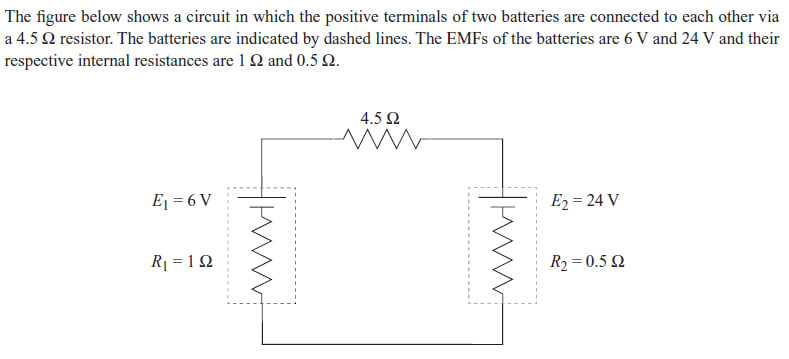
Here is a picture of the question:
Purple_circuit_10_scxix3.jpg


This is not homework.

I would like to know, the formula for EMF (from what I have found online) is e = V + Ir where e = the electromotive force, V is the volts, I is the current, and r is the internal circuit. But the answer for this is simply "24 - 6 = 18", and the explanation for this is that the batteries's positive terminals are facing the each other so the voltage is working against each other, and the 24V one is going to over power the 6V one. That is all logical even if you don't have any electrical circuit knowledge, but what I don't understand is what happened to the e = V + Ir formula? Why was this not used at all? People who were discussing this question also said that if the batteries were facing the same way, the EMF would simply be 24 + 6 = 30. Again, the formula is not used. Is the EMF simply a sum of the 2 battery's voltages?

Thank you in advance.
 
Replies continue below

Recommended for you

The formula is not used because the answer is given - the EMFs of the two cells are plainly stated and EMF is constant. With the cells in opposition the EMFs for the circuit subtract.

EMF is what adds energy to the system and that energy is added at 18V.
 
Dear Mr Total Novice
There are numerous good advice. I am confused too. I try to look at it as following:
1. Remove the 4.5 ohm load , the LHS battery EMF is 6 V and the RHS battery EMF is 24 V.
Note: (a)This is the EMF voltage across the battery when NOT connected to any load = open circuit voltage.
(b) the battery internal resistances of 1 Ohm and 0.5 Ohm respectively, are irrelevant.
2. When the 4.5 Ohm load is connected:
2.1 the loop resistance R=4.5 + 1 + 0.5 = 6 Ohm.
Note: Both batteries internal resistance of 1 Ohm and 0.5 Ohm are considered connected in series with the load 4.5 Ohm.
2.2 The current I = E/R ...A . i.e. 18/6 = 3 A
Note: (a) E = 24-6 = 18 V
(b) battery internal resistances are irrelevant.
2.3 the RHS battery is discharging 3 A
Note: (a) voltage drop across the battery internal resistance vd = 0.5 Ohm x 3 A = 1.5 V .
(b) the voltage across the battery would be EMF - vd = 24 V - 1.5 V = 22.5 V.
3. Summery: The voltage across RHS battery = 22.5 V .
Che Kuan Yau (Singapore)


2.3 the RHS battery is discharging 3 A
And the LHS battery is charging 3 A.
But, The respective terminal voltages are now LHS 9 Volts, RHS 22.5 Volts.
The voltage across the 4.5 Ohm load is 13.5 Volts.
The internal voltage drop on charging is the opposite sine to the voltage drop on discharge.
Better to stick to EMF and KISS.
Final proof:
13.5 Volts/4.5 Ohms = 3 Amps.

--------------------
Ohm's law
Not just a good idea;
It's the LAW!
 
Dear Mr Dear Mr Total Novice

Further to my earlier post, I would like to add the following:
1. The loop current is 3 A.
2. The RHS battery is discharging 3 A (i.e. current flow out of the RHS battery terminal + to LHS battery).
3. The voltage across the load resistor is V=I x R = 3A x 4.5 Ohm = 13.5 V (i.e. current flow from RHS towards LHS).
4. The voltage across the load resistor would be 13.5 V (i.e. RHS + and LHS - )
Che Kuan Yau (Singapore)
 
Firstly I apologise for "ignoring the signs". I don't study electrical circuitry and learnt the basics just for this question so I don't really know how to do that.

I would like to check that I understood something by asking a few questions and answering them myself.

1. What kind of circuit would you say this is, closed or open? I think it is closed.
2. Would you say there is a load on the circuit or there is no load? I would say there is a load and it has the resistance of 4.5 Ohms.

Consequences:
Since the batteries are connected to something (a resistor with resistance of 4.5 Ohms), and the circuit is closed, then "the voltage of the battery = EMF + IR". And since we are given the voltage already (24V and 6V), if we rearrange the formula to have EMF on its own, then it would be voltage of the battery - IR = EMF.
I am going to call the voltage of the battery Voltage B.
I*R gives you Voltage. I will call this Voltage Y.
Therefore for this question at least, EMF = Voltage B - Voltage Y = EMF.
Voltage B would be 24 because it is the biggest. Is that the correct reason? And because we are looking at the difference between the 2 terminals, the R in I*R = Voltage Y would be of the other battery, with voltage 6.
We do not know the current, I.

Am I correct so far?

So now we have:
EMF = Voltage B - Voltage Y where Voltage Y is I * 6.
=
EMF = 24 - I*6.
We still don't know I.

As an alternative, I tried to do the above in conjunction with what 3DDave said which was

so that I = 3.
But substituting 3 into the EMF equation gives me 24 - 3*6 = 6, not 18.
 
@Che12345,
I completely agree with most of the things you have said. It is clear to me that the EMF is the voltage across a battery when it is NOT connected to a load. However the circuit in the question has a load. You can see it, it has a resistance of 4.5 Ohms.
So then my question is, whenever a question asks for the EMF, can I just mentally remove or completely ignore any load and pretend it is an open circuit, then find the difference between the two voltages? Is that how simple it is?
 
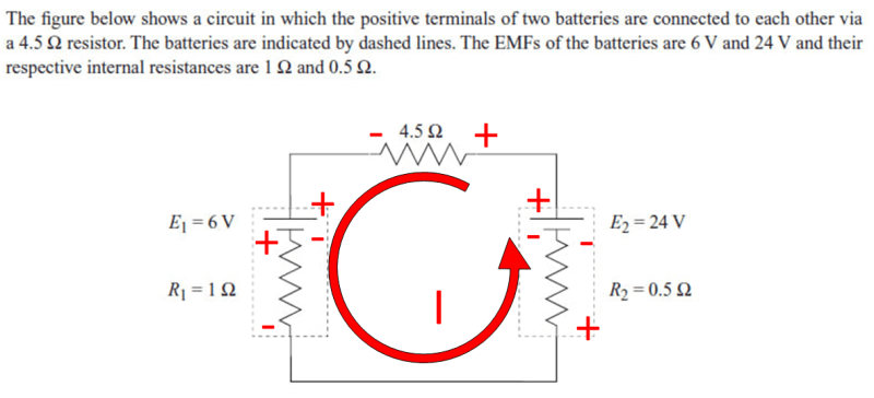
This is the OP's circuit annotated. We arbitrarily assert that the conventional current is flowing CCW, although we pretty much know that has to be, since the larger battery will dictate the current flow.

Since conventional current rules make the incoming end of a component positive, the signs will correspond to the voltages measured across each resistor, assuming the current direction is correct. This corresponds to the equation I originally posted. When the equation is solved, the current is positive 3A, which means that the CCW direction was correct. If we had asserted the current was CW, then the solution to the that loop equation would have been -3 amps, thus correcting the flow direction to CCW.

If the two battery voltages are swapped, then the conventional current would correctly flow in the CW direction.

circuit_zkvgx5.png


TTFN (ta ta for now)
I can do absolutely anything. I'm an expert! faq731-376 forum1529 Entire Forum list
 
So then my question is, whenever a question asks for the EMF, can I just mentally remove or completely ignore any load and pretend it is an open circuit, then find the difference between the two voltages? Is that how simple it is?

No, that's only the answer to that specific question, for that specific circuit. What would you have done had there been a current source in the circuit? Or, had the circuit had multiple loops?

TTFN (ta ta for now)
I can do absolutely anything. I'm an expert! faq731-376 forum1529 Entire Forum list
 
"EMF is the voltage across a battery when it is NOT connected to a load"

EMF is a constant and is given in the diagram.

What isn't constant is the voltage across the internal resistance. It doesn't matter what is hooked up, at least until the chemistry inside the cell is consumed.

If they want the EMF it is what is stated on the diagram
If they want the battery terminal voltage for that circuit, that's also been calculated here but is not EMF.
 
Dear Mr Total Novice (Electrical)(OP)
".....So then my question is, whenever a question asks for the EMF, can I just mentally remove or completely ignore any load and pretend it is an open circuit, then find the difference between the two voltages? Is that how simple it is?......"
You may answer as following:
1. The EMF of the LHS battery is 6 V and the RHS battery is 24 V ; when the circuit is Open without may current flowing through.
2. When the circuit is closed with a load of 4.5 Ohm, with current of 3 A flowing; the voltage ( NOT EMF) or call it [potential difference] at each point:
(a) across RHS battery is 22.5 V,
(b) across load is 13.5 V , (i.e. RHS + and LHS - ),
(c) .....
In this way you answer the question in full, with no ambiguity; on the terminology used between EMF and potential difference.
Che Kuan Yau (Singapore)

 
Okay I am going to make some observations here:
Some people seem to say EMF is not the same as voltage (and I would agree as my research told me so, but I do not understand the difference). For example, Che12345 wrote:

(here it is claimed that voltage is not the same as EMF)

but then at times it seems that EMF IS the same as voltage for example:
by Che12345:
The [b said:
EMF[/b] of the LHS battery is 6 V and the RHS battery is 24 V]
(here EMF was used instead of voltage)

and by 3DDave:
EMF is a constant and [b said:
is given in the diagram[/b].]
(nowhere in the diagram is anything labelled as 'EMF', thus this to me says EMF must be the same as voltage, as voltage and resistance are the only things labelled and it sure is not resistance so must be voltage)

My goal is to figure out a rule here so I know what to do if I come across a similar question in the exam (as I mentioned, this is from a practise paper. The practise paper has questions on various topics including electrical circuits. The real exam will have questions about the same topics but may or may not ask a similar question/s (for example, in a different practise paper, the electrical circuitry question was about which light bulb will be brightest). At the moment, it seems like EMF is treated as the voltage (even though they are not the same) on purpose, and the rule is simply to ignored the load on purpose, in order to get the answer of 24V - 6V = 18V (I say 'on purpose' because despite definitions saying EMF is only the voltage when there is NO current nor load, and there obviously is a current and load, the solution just went 24V - 6V = 18V and the only way to do that despite the definitions and violations of these definitions is to ignore the load and current on purpose).

And thank you IRStuff for the annotated diagram.
 
These questions are not done in a classroom, it is from a practise booklet created by the examiners.


So, the first question should be what does the practice exercises done before the practice exam define EMF as?
 
EMF is given in the problem statement with identical values for E1 and E2. Since they are identical they cannot be in-circuit voltages.

They are trying to see if you know what EMF is and are adding information to get you to calculate voltage drops and in-circuit voltages and waste your time.
 
This problem is really old, and the apparent answer is supposed to the EMF of the simplified circuit, which is the difference of the battery voltages, which makes sense that the answer might be 18V


TTFN (ta ta for now)
I can do absolutely anything. I'm an expert! faq731-376 forum1529 Entire Forum list
 
Forget Internal resistance for now.
Forget voltage drops for now.
Forget the resistor for now.
Forget charging and discharging for now.
The question was concerning EMF.
The answer is 18 Volts EMF.
+24 Volts EMF - 6 Volts EMF = 18 Volts EMF.
Keep working on it until you are able to successfully subtract 6 V from 24 V and get 18 V.
Don't try our patience any longer.


--------------------
Ohm's law
Not just a good idea;
It's the LAW!
 
More info - from an test-prep site:

-----

The figure below shows circuit in which the positive terminals of two batteries are connected t0 each other via a 4.5 Ohm resistor: The batteries are indicated by dashed lines. The EMFs of the batteries are 6 V and 24 V and their respective internal resistances are 1 Ohm and 0.5 Ohm.

10) What is the resultant EMF in the circuit? 6V 18 V 24 V 30 V

11) What is the current flowing in the circuit? 5A 4A 3A 1A

---

The amusing answer transcript:
Hello. The question is taken from physics and the question is The figure shows like it. In which the positive terminal of the two batteries are connected via a 4.5 register. The batteries are indicated by the dashed line. The M F of the battery are six for 10. 24 world and their respective internal resistance is r one moment 50.5. So what this stuff is R E M F Industry ticket. Okay So EMF is six whole days here. 24 World is here. So net IMF will be equal to 90 MF will be equal to 24 world minus six world. So that is equal to 18 world. It involved is an 80 M. F. Now what we have to evaluate what is the current flowing in the circuit. So in order to evaluate the current we have to use the Kv L O. Okay so I double the distances 4.5 and then six words and then there is a resistance Having a resistance value one then there is a battery. 24 world and then resistance it is further connected. It is 24 world and 0.5 words mm Okay so let us use the Gabriel ice to govern. So that is I into one. So one I -6 plus 4.5 into I Plus 24 and plus 0.5 in two I 0.5 Y is equal to zero. So the guarantee 0.5 into 4.5 is five and +16 I that is equal to minus of 80 involved. So I. easy. Sorry. And Bill, actually this is involved. I is equal to minus three mps. Okay? But so from here, the direction of covered must be opposed. So I will be equal to three mps and the direction of current either anti clockwise direction. So the required current flow into the psyche. It is three mps. So this is the required solution for the given question. So hope this clears your routing.
 
This is not done as part of a course in a classroom, the exam is also not part of any course. It's like IELTS - you can sit the exam if you want and there is no official curriculum for the exam content.

This is because you're NOT supposed to use the test to learn; you use the test to verify your learning.

But I still haven't gotten an understandable definition of EMF so no, I don't know what it is.

I did actually explain it, EMF -- electromotive force; it's whatever "thing" there is in a circuit that supplies current flow. Since resistors aren't active devices, they cannot supply current, which leaves the two batteries.


TTFN (ta ta for now)
I can do absolutely anything. I'm an expert! faq731-376 forum1529 Entire Forum list
 
I just wanted to provide some context on this exam for people who have been helping me.
This exam is called the gamsat, interested parties can look it up. Anyone can do it regardless of your background. The exam covers biology, chemistry and physics but not in the conventional factual information way. It can ask questions from a mix of any topics in those three areas in any ratio. It often asks convoluted and flawed questions that use scientific premises to ask "logic" related questions. You may come from an entirely non-science background, eg you could be an actor for all they care, and have never learnt maths or any form of science so it is entirely possible and 100% normal to have not learnt or studied anything about electrical circuitry (or biology or chemistry), so there is no "learning" to speak of.

Now I would like to just say thank you to everyone who took the time to help me with this, I did a of research before hand but it is not the same as getting answers from humans. Thanks again and have a nice day.
 
Status
Not open for further replies.

Part and Inventory Search

Sponsor