Continue to Site

Eng-Tips is the largest engineering community on the Internet

Intelligent Work Forums for Engineering Professionals

  • Congratulations SDETERS on being selected by the Eng-Tips community for having the most helpful posts in the forums last week. Way to Go!

How to control 4 cylindrical pockets 2

Status
Not open for further replies.

Rwelch9

Mechanical
Apr 22, 2020
116
RW_Drawing_s1sg64.jpg


Hi guys,

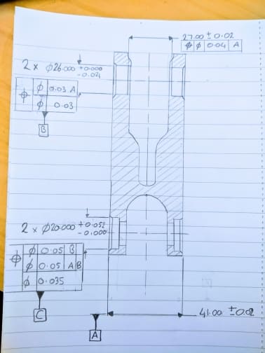
Can anyone point out any flaws you see with these call outs on this drawing.

The idea is the best way to control and dimensions 4 Cylindrical pockets / with the front and back being as close as coaxial as possible.

Thanks

Ross
 
Replies continue below

Recommended for you

Have you ever answer to what standard are you using?
You put a bunch of threads recently, but never a definitive answer or am I missing it?
 
greenimi ,

I am sure the customer is using ASME Y14.5

Is there different standards within this ?

Thanks

Ross
 
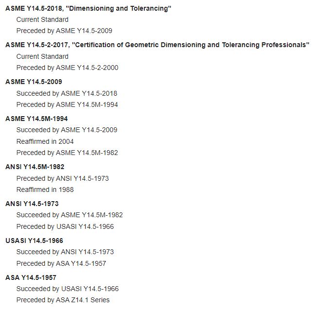
The critical missing info is what year you are utilizing. There are large differences between each revision, it matters quite a bit.

Y14.5_bv5wmg.jpg
 
Perfect ,

it will be the current standard i presume , which i will double check.

These are new prototype components so i would assume the latest standard would be used.


Are you allowed to use old standards for new parts ?

Thanks

Ross

 
Who develops the drawings for these components? I am guessing by your questions that you are design responsible. In that case, it is up to you to determine the standard. If not, then you must check with your customer. The latest version is 2018, yet many companies are still utilizing 2009. Even still some companies utilize the 1994 version, and its not uncommon to see legacy parts with drawings compliant to 1994 or older.

There is no requirement that one utilize the latest standard for a drawing of a new part - I could make a brand new drawing and utilize ASA Y14.5-1957 if I wanted to, however it usually behooves a company to try and update their practices to the latest standard because of improvements, clarifications, and added controls. That said, whatever it is drawn to must be utilized to evaluate said drawing (and for inspection/etc..) unless noted otherwise by the design responsible party or on the drawing itself. Sometimes older drawings cannot even be interpreted with newer standards - for example Symmetry and Concentricity have been totally removed from Y14.5-2018, a drawing compliant to Y14.5-2009 that utilizes these controls would have to be interpreted with the original standard, even if allowed to do otherwise by the aforementioned methods.
 
Totally understand ,


Going with either the latest version or 2009 version . Would the call outs in my sketch hold up with you guys ?

Thanks

Ross
 
Without nitpicking too much (cough, attachment of the datum feature symbol A, cough) it will certainly accomplish what you want - though the top frame (PLTZF) of your composite tolerance cannot have a reference to only B. You must the same datum feature references and in the same order of precedence in each frame. If you truly want to do this, Multiple Single Segment would allow that. You also have several frames with the same size tolerance zone, just with different datum features - this is relatively redundant (ie: if a hole conforms to 0.03 position to |A| it will certainly conform to 0.03 datumless position) and even if its not wholly redundant (ie: 0.05 position to |B| and 0.05 position to |A|B| - assuming they were applies in a multiple single segment, since as I said its not valid for composite) I'd question why you needed such refinement.

There are other methods, including utilizing a single profile tolerance combined with "HOLES INDICATED Y" or some similar note if all four holes can be held to the same size tolerance zone in basic location to each other instead of establishing one set of holes as datum feature B and controlling location from there.
 
Please nitpick,

Every ones help and knowledge is fantastic.

Holding my Datum B to say 0.05 to A , does then in turn control the true position between the pockets and the perpendicularity between the Datum Feature A ( Plane ) to Datum feature C ( axis combined by the two top pockets )

What i am looking for is the pitch between Datum B + C to be tolerance differently to the parallelism between the two axis .

I don't think i am understanding composite tolerancing enough.

Which something i will have to look at .

Thanks

Ross


The top level of a composite tolerance controls both orientation and location both to the datum references and to each other.
Lower levels control only orientation to any duplicated datum references and orientation and location to each other.
When there is no reference at a lower level to any datum reference then orientation and location are controlled only to each other.

It is only sensible when each descending number of datum references is accompanied by a decreased tolerance allowance.

 
Thanks 3DDave,

Would you agree , this specific type of tolerancing is more difficult when using it to actually control Datum Features to one another .

 
4_Cylinders_Datum_idea_p4zh6z.jpg


Hi guys,


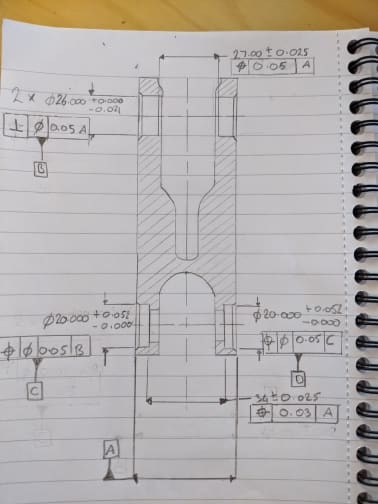
Does this 2nd attempt make more sense

The reason the back two are 2x and the front is not,

is the depth of the front two would very difficult to check them as cylinders as they are so shallow.
 
It is much easier to understand this if you buy a copy of the relevant standard and read it.
 
IMG_20200501_104115_chnv5u.jpg


3DDAVE,

Thanks for the previous help,

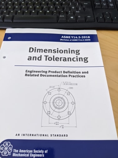
I have purchased this book yesterday so i have a lot of catching up to do .

Ross
 
Rwelch9,

Allow me to share some loose thoughts that come to my mind after reading through this thread (I see that you started multiple threads which all seem to circle around the same part/drawing):

-- The fact that you have bought 2018 version of Y14.5 does not have to mean that the your customer uses this version of the standard too. Each version is different from the others, so I would really encourage you to clarify this with the customer before you go any further.

-- It is very difficult to say whether certain dimensioning and tolerancing scheme is really correct just by looking at the drawing. GD&T philosophy is that dimensioning and tolerancing should really be based on how the part functions. In other words, you may have a perfectly looking drawing from semantic point of view (all callouts defined on it will be fully according to the rules defined in the standard), but the definition itself will be far from perfect, because it will not capture the functional requirements of the part properly. What I am trying to say by this is that to asnwer this kind of question one usually needs to know how the discussed part is oriented and located in the assembly. This greatly helps for example in determination if datum features have been selected correctly.

-- On your 2nd drawing, removal of 2X from the front shallow holes will not make the establishment of their axes any easier. The axes of each individual holes will have to be established anyway.

-- On your 2nd drawing, the perpendicularity tolerance wrt A applied to both front holes should be changed to position wrt A to avoid incomplete specification. Current scheme does not control mutual relationhip (spacing) between axes of the holes.

-- I would not give up on a thought to apply a composite position tolerance to both front holes (of course assuming it functionally makes sense).

-- If the drawing is in millimeters and you really want to follow the standard, you need to correct the way the decimal places have been expressed for almost every dimension. In 2018 version of Y14.5 you will find the rules for this in para. 5.3.1.

-- The diameter symbol preceding the tolerance value inside the feature control frame (FCF) shall be in the same compartment of the FCF as the tolerance value (i.e., no separate compartment for the diameter symbol is needed).

-- What about the 2 small holes coaxial with the front holes? Can they be controlled as a group relative to a global datum system (say, |A|B|C| or |D|, where D is an axis established from both dia. 20 bores) or does each of them must be controlled individually to its corresponding bore?
 
pmarc

yes slightly different although all evolving around coaxial cylinders.

This one is slightly different as its 4 ( two sets of coaxial cylinders ) really the only important thing on the component is the relationship between the for cylinders.

I cannot see any examples of this anywhere . My problem is i would find it okay dimension features to a Datum . However trying to dimensions these 4 cylinders to each other and using them as a Datum .

This is something i have never seen or done before.

: regarding the book ( is there a vast difference between different one ) ?

: So changing Datum B to positionally to Datum feature A ( Rather than perpendicular ) this will then control the pockets together in both axis, then it will control also the perpendicularity.

: Thew two small holes coaxial with the front holes ( although not showing are threads )


Any help on how best to control the relationship between these 4 pockets and using them as the Datum , would seriously be appreciated. As i cant find any similarities anywhere.


Thanks

Ross
 
I am not sure I understand everything from your last post, so forgive me if this reply does not address all your questions well.

-- The relationship between 4 cylinders can be addressed by applying position tolerances relative to datum A only. There is a concept in Y14.5, called 'simultaneous requirement', that says that unless otherwise specified, the features controlled with position or profile tolerances that reference the same datums, in the same order, and at the same material boundary shall be considered a pattern. In your case the position tolerances relative to A only would create a group of 4 cylindrical tolerances zone (2 pairs of 2 coaxial cylinders) perfectly perpendicular to the datum center plane A and spaced at basic distance apart (which by the way is missing on your drawing).

-- Regarding the difference between different versions of Y14.5. Some will say the differences are minor, some will say otherwise. That depends on who you ask. In the parallel thread started by you about straightness tolerance, I gave an example of a difference between '94 version and higher versions. And there are more. For instance, '94 version did not show any examples of composite tolerances with more than 2 segments and many people literally took this as no-no for three-segment composite callouts. As you already noticed in another thread, newer versions of the standard clearly allow for this kind of callouts.

-- Yes, in addition to being a perpendicularity control relative to A, the position applied to 2 datum features B will also control axes offset. Perpendicularity tolerance alone is not capable of controlling the latter.
 
Pmarc,

this is perfect thank you .

i will look into everything you stated.

yes there is a basic dimension for the pitch between them in the actual drawing of the component .


Thanks

Ross
 
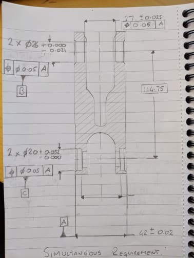
SR_Drawing_v9nblq.jpg


Updated Drawing trying incorporate you guys advice.

My question if this attempt at using simultaneous requirements. To create a pattern is correct.

Does that mean the bottom two cylinders together would have to be with 0.05 positionally of the top two cylinders.

whilst both set of cylinders would have to perpendicular to Datum A within 0.05.

Thanks

Ross
 
If you are establishing datum B and C and not using them in other FCF's I think is useless.
Why do you need B and C?
Maybe am I missing something, but I did not understand their scope.

 
Status
Not open for further replies.

Part and Inventory Search

Sponsor