Eng-Tips is the largest engineering community on the Internet

Intelligent Work Forums for Engineering Professionals

How to model part with specified minimum dimensions 1

Status
Not open for further replies.

cinnamongirl

Mechanical
Jan 18, 2011
106
0
0
US
How do I model 3D part features that are only specified by minimum dimensions? The drawings I'll be making from these 3D parts will only call out minimum dimensions on certain features because that's what the ASME standards specify.

For example, I have a coupling which must maintain a minimum wall thickness according to the ASME standard. Do I model it according to the minimum thickness? Or do I make the walls slightly thicker and override the value on the drawing dimension to specify the minimum? The coupling is cylindrical and if I make the walls slightly thicker it will minimize the amount of machining necessary because the overall diameter will be closer to diameter of the stock material.

Thank you.
 
Replies continue below

Recommended for you

Cinnamongirl,

Is your 3D model actually being used for product definition for example being fed directly to the production process through 3D printing or being referenced on the drawing somehow (ie: basic profile defined by 3D CAD data)? If not it likely matters very little, your drawing would be the definitive reference in that case. Modeling at nominal is usually good practice as ctopher mentioned, unless internal or standardized requirements for a particular part/feature type dictate otherwise.

That said, regardless of what your particular standard dictates I would be very careful with specifying only MIN or MAX of any type of feature. If your drawing or referenced standard does not specify or limit the other bound somehow you should make sure you're okay with the referenced dimension approaching zero (if MAX) or infinity (if MIN). If your drawing adheres to Y14.5, it outlines this nicely. Even if not, it's still a good general rule:

ASME Y14.4-2009 said:
2.5 SINGLE LIMITS
MIN or MAX is placed after a dimension where other elements of the design definitely determine the other unspecified limit. Features, such as depths of holes, lengths of threads, corner radii, chamfers, etc., may be limited in this way. Single limits are used where the intent will be clear, and the unspecified limit can be zero or approach infinity and will not result in a condition detrimental to the design.
 
ctopher said:
I always model to nominal.
ie: .375 +/-.005, I will model to .375.

Just for me to be clear,

1) .375 +/-.005
2) .380 +0/-.010
3) .370 +.010/-0

For above three, "average" is always .375, but "nominal" is 1) .375, 2) .380, 3) .370, respectively.
Is it correct?
 
I don't often have minimum dimensions. Maximum is much more common for features such as inside corner radius or a sharp corner break edge. In those cases I generally model at half the maximum as that's the nominal between zero and the maximum. Sometimes if I know zero is impossible, like an inside corner radius I will model at the median between the sharpest possible tool radius and the maximum. With minimum dimensions, it's more difficult because if the upper limit is truly infinite than the nominal value is also infinite. In the OP case of a minimum wall thickness, I certainly would not model at the minimum because that would give you no margin. Particularly if you can reduce machining time and there for cost I would just make sure that when you do a worst case stack up of you dimensioning scheme tolerances you are thicker than the minimum in the spec. Preferably with some extra margin.

----------------------------------------

The Help for this program was created in Windows Help format, which depends on a feature that isn't included in this version of Windows.
 
Thank you all for the replies. To answer some of the questions, the 3D model (exported in STEP format) will be handed to an outside machine shop along with a drawing driven by the original 3D file. Is it acceptable practice to override the dimensions in the drawing (albeit stated as a minimum) if I make the features a slightly different size?

On the other hand, if I model the part according to the minimum specs I assume that the machinist can make the necessary adjustments during the CNC programming.
 
Woosang,

For what its worth, personally I typically use the average or middle point of the tolerance bound interchangeably with the term "nominal". Unless otherwise specified or instructed, this is what manufacturing will try to hit regardless if the tolerances are applied unilaterally (+0/-.01) or bilaterally (+/-.01) or otherwise. It is also possible (though rare) to apply a tolerance which the notated value is not even within the tolerance band ie: .375 +.005/+.010 where referring to .375 as nominal would be slightly confusing - at least to me.

Perhaps this isn't a proper or precise use of the term "nominal". In that case I would change my recommendation to default to the middle/average of the tolerance band - ESPECIALLY if this 3D CAD data has any chance of being fed directly into the production process. If a model must be used for programming for example 3D printing, CAM for machining (especially 3D toolpaths), etc.. and a model is already available chances are it will be used - if it is not modeled to be in the middle of the tolerance band the chances of someone not taking the time to remake the model or adjusting the toolpaths/etc.. to account for this becomes much higher, which could cause issues downstream.

I'd be interested if someone has a contrary opinion. Modeling a feature at .375 when the designer desires to have the print show .375 +0/-.010 certainly makes the designer's life easier, and if the 3D CAD data has zero chance of being fed to manufacturing then it probably doesn't matter much either way.

A few insights on "nominal" from Y14.5:

Y14.5-2009 said:
1.3.56 Size, Nominal
size, nominal: the designation used for purposes of general identification.

Not super helpful or specific. I guess one could interpret this to mean the stated value on the drawing (ie: 1) .375, 2) .380, 3) .370 on your 29 Jan 20 04:44 post) not taking into account tolerances. Y14.5-2018 uses the same definition but adds a reference to USAS B4.1 meaning presumably ASME B4.1 - a brief reading of B4.1 seems to support this use of the word nominal.

Y14.5-2009 said:
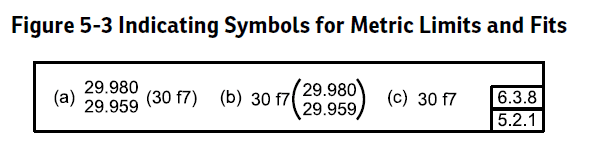
2.3.1 Millimeter Tolerances
Where millimeter dimensions are used on the drawings, the following apply.
(a) Where unilateral tolerancing is used and either the plus or minus value is nil, a single zero is shown without a plus or minus sign. In this example the 32 value is the nominal size.
EXAMPLE:
32 0/-0.02 or 32 +0.02/0

This would reinforce your interpretation (29 Jan 20 04:44). The same section (b) reiterates this. Interestingly Y14.5-2018 removes this reference to nominal in the section on millimeter tolerances (see below). Additionally, the inch tolerances section in both 2009 and 2018 is devoid of any reference to "nominal".

Y14.5-2018 said:
5.3.1 Millimeter Tolerances
Where millimeter dimensions are used on drawings, the following apply:
(a) Where unilateral tolerancing is used and either the plus or minus value is 0, a single zero shall be shown without a plus or minus sign.

An important note has been added in Y14.5-2018 which should always be kept in mind, regardless of how one decides to use the term "nominal" :

ASME Y14.5-2018 section 4.1 Fundamental Rules said:
(q) UOS by a drawing/model note or reference to a separate document, the as-designed dimension value does not establish a functional or manufacturing target.
 
Is it acceptable practice to override the dimensions in the drawing (albeit stated as a minimum) if I make the features a slightly different size?

Unless your internal requirements dictate otherwise, I would say model to nominal/average* especially as I said the 3D CAD data is in any way available to manufacturing. Again, I'm going to sound like a broken record but I would be very careful with your use of minimum limits - personally I would fully define the product ie: your coupling by ID/OD and their relative position and if necessary add a note "MIN WALL .xxx PER ASME xx.x-xxxx" or similar. I wouldn't rely on the specification of minimum wall thickness for full definition of the features involved.

On the other hand, if I model the part according to the minimum specs I assume that the machinist can make the necessary adjustments during the CNC programming.

See my above response (29 Jan 20 17:39). Providing 3D CAD data directly to manufacturing and assuming they'll just make the adjustments could set you up for some headaches. Should they? Yes. Will they? Maybe, maybe not. In my experience, unless you must for any particular reason I wouldn't rely on that.

*Edit: I misread, I have modified my statement.
 
cinnamongirl,
Model to nominal, create the drawing to this. On the drawing dimensions, add tolerances as required. Overrides over what the actual model is can cause issues later with CAM.
Let the machinist use the actual model (or drawing if not CAM) to program.
The STEP files (or other dumb solids) can be used to send to customer, 3D print, etc.

ctopher, CSWP
SolidWorks '17
ctophers home
SolidWorks Legion
 
Pervasive dogma in the CAD universe is that the 3D model you document your design with must be the one you build from. This is pleasing to simple, sclerotic minds but often leads to problems.

There is no "always". Maybe a "most often best", depending on process and industry. But no "always".

Export a special model for the build and document in the contract or work order.
 
You definitely do not want to model at the minimum wall thickness and expect your vendor to add material. That is a recipe for disaster. Just because a spec says you need a minimum wall is NO REASON to model that. All you need is a dimensioning scheme that ensures the wall can never be less than the minimum in the spec. If you want you can add a note referencing the spec with the minimum wall thickness. If you send out a model with the minimum wall you will probably get back a part with the wall less then the minimum in some places.


----------------------------------------

The Help for this program was created in Windows Help format, which depends on a feature that isn't included in this version of Windows.
 
cinnamongirl,

What shape are the surfaces between which the minimum wall thickness is specified? What other tolerances involve those surfaces?

What is the wall thickness of the most likely manufacturing target geometry? What is ideal for the end use?


pylfrm
 
chez311 said:
This would reinforce your interpretation (29 Jan 20 04:44). The same section (b) reiterates this. Interestingly Y14.5-2018 removes this reference to nominal in the section on millimeter tolerances (see below). Additionally, the inch tolerances section in both 2009 and 2018 is devoid of any reference to "nominal".

Quote (Y14.5-2018)
5.3.1 Millimeter Tolerances
Where millimeter dimensions are used on drawings, the following apply:
(a) Where unilateral tolerancing is used and either the plus or minus value is 0, a single zero shall be shown without a plus or minus sign.

Thank you for pointing that.

Let's consider fit tolerance as shown below captured from Y14.5-2018.
Take this dimension is for a tab width or a shaft diameter (assuming there is a diameter symbol), and the model flows down to CAM.
1. What size would you model it? 30, or something close to 20.970? What we actually do is modelling at 30. (Of course 2D drawing associates the model)
2. Which dimension would you call nominal? 30, or something close to 20.970?

image_vjevus.png
 
@cinnamongirl: Nothing prevents you from modeling your parts at the least material condition. With my CAD package, I would model that feature at LMC and then when I place the dimension, I would add the qualifier MIN to that dimension. The number will be correct, and would likely be updated if your model is changed at a later date.

I try to avoid forcing dimensions as much as possible. Forcing dimensions breaks things at some future time where a different engineer might be caught unaware.

ASME Y14.41 section 9, especially 9.2.3, is useful.

** Soapbox **

Something that a couple people alluded to, but didn't state explicitly, is the definition of terms. I try not to be too pedantic, but this is a topic that I've had a lot of fun with over the years. Woosang's post above is so perfect. What is nominal?

Nominal is not equal to mean is not equal to average is not equal to target or intent.

In fact, I would go so far as to say that it's inappropriate to compare these terms. They are all completely separate things. There is only one case where nominal and average are the same: bilateral tolerances like 1.00 +- .03. Yes, that case occurs frequently. A lot of confusion stems from applying this idea everywhere, though.

As an example, a nominal 1 inch pipe thread doesn't even have a 1 inch dimension on it anywhere. Nor does a nominal 2x4 stud have a 2 inch dimension on it.

Another example, a nominal 1/2 precision shaft might be specified as .4995 - .4998 per the ASME fits and finishes or perhaps .5000 -.0002, -.0005. The average of those two values is not equal to nominal shaft size and part made blindly to a nominal .5000 would be out of spec. In the later example of a dimension and tolerance, you would call the nominal value the .5000 part. That doesn't mean it's the middle value. But where to model such a shaft? Good question. I would choose to model this particular shaft at the maximum material condition.

I like limits of size in a lot of cases. A very good machinist friend likes to know what his "target" value is. There are very good reasons for both approaches to specifying your parts.
 
I missed dgallup's point and it is valid. The ASME spec you are using requires a minimum dimension. If your model and dimensions are greater than that, then you have complied with the ASME spec.

I personally would still model at minimum though. If you are really worried to get that particular dimension complied with, make sure it is on an inspection report/request/plan if your company employs such things.
 
Woosang,

My interpretation of Ctopher is that the nominal dimension is .375".

.375[±]0.005"
.375+.010/-.000"
.375+0/-.010"
.375+.015/+.005"

.375 is the design intent. The tolerance makes the part work.


--
JHG
 
cinnamongirl,

In general, I agree with Ctopher. I prefer to model to nominal dimensions, and then apply tolerances to my drawings. How will your fabricator manage your documentation?

[ul]
[li]You send a PDF of your drawing and a STP file of your model. Your fabricator carefully studies your PDF file. The STP is used for visualization purposes only.[/li]
[li]The fabricator ingnores your drawing and uses the 3D CAD file to make the part.[/li]
[/ul]

A well prepared 2D drawing provides a precise, legal definition of the part that you will accept and pay for. Are you and your colleagues good at GD&T? Do your purchasing people respect your documentation, send out the files you require, and let your participate in any vendor discussions?

--
JHG
 
Thank you all for your responses. Here's how I chose to document a cylindrical coupling with a socket.

The minimum socket depth requirement according to the standard spec guide is 3/8", and the parts that were previously made have a slightly larger depth of 7/16". In order to maintain some consistency with the new parts we will be ordering I modeled my part with a socket depth of 7/16 inches, dimensioned it accordingly and manually added the minimum requirement of 3/8" for inspection purposes in parenthesis. Does this meet CAD and dimensioning standards?

Capture_hsqgna.png


An outside machine shop will be using my 3D model to CNC the parts but I want to leave some indication of the MIN requirement from the spec sheet in the drawing.

(by the way, for the other dimension requirements in that image, shown in limits, I used the average of each limit range to build the 3D model)
 
Status
Not open for further replies.
Back
Top