Eng-Tips is the largest engineering community on the Internet

Intelligent Work Forums for Engineering Professionals

How to quantify features

Status
Not open for further replies.

G_Apache

Mechanical
Jul 7, 2022
6
0
0
US
I'm looking to see what the proper way to quantify multiple features is.

Quantity_blg2xm.png


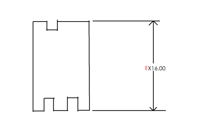
In a situation like this where there are 2 surfaces for one datum and 3 surfaces for another, how do you express that the 2 surfaces are, say, 16mm away from the 3 surfaces? Should the quantity be dropped, be 2X, or be 3X?
 
Replies continue below

Recommended for you

What standard are you using?

If you're just asking about specifying basic dimensions, extension lines as 3DDave mentioned are acceptable and you can ignore the rest of my response. If you're asking about also how to specify how to specify/apply a tolerance to these interrupted features, then the below might be relevant:

For ASME Y14.5 it depends on whether you want them to conform to a single tolerance zone or multiple independent tolerance zones. <CF> Continuous Feature and/or a profile tolerance might be one way to achieve the former (if we're nitpicking, profile tolerance without <CF> is still multiple tolerance zones but as long as SIM REQ applies or "nX" is used they are locked wrt each other), if a profile tolerance is not used or SEP REQ invoked "nX" might be one way to achieve the latter, though if a profile tolerance is not used and <CF> is not specified for an interrupted feature like you have shown (has both opposed and unopposed points) measurement/interpretation might get a bit sticky. Note, in these cases extension lines do not imply a continuous feature or pattern.
 
IAW Y14.5-2018 ¶6.3.23
...extension lines by themselves do not indicate a CF.

Extension lines across the gaps is an old method which has been brought into question with the 2018 release of the standard. Based on that, (if CF is not used) I would have to say the qty in the original question is 4X.


"Know the rules well, so you can break them effectively."
-Dalai Lama XIV
 
It's a good thing I don't have the 2018 release then. I'll update when both Y14.5.1 and the GDTP tests reflect their confidence in that version. I'd say that buys about a decade.

In any case there are 3 pairs of opposed surfaces, and there are 3 areas that are unopposed.

In any case, the extension line(s) shows the one dimension applies to all the surfaces in line with it, so the count is "1".
 
Hi, G_Apache:

Technically, it is 6x as there are 6 features (2 x 3).

I would use dimension 16 BASIC with an CF symbol.

Best regards,

Alex
 
Ewh/3DDave,

That same verbiage exists in the 2009 version as well.

Y14.5-2009 said:
When using the continuous feature symbol, extension lines between the features may be shown or omitted; however, extension lines by themselves do not indicate a continuous feature. See Figs. 2-8 through 2-10.
 
I would use dimension 16 BASIC with an CF symbol.

<CF> should not be applied to a lone basic dimension.

ASME Y14.5-2018 para 6.3.23 said:
The “CF” symbol shall be applied to a size dimension of an interrupted regular feature of size, adjacent to a geometric tolerance for an interrupted surface, or adjacent to a datum feature symbol applied to interrupted features.
 
Chez - well that, that just goes to show how this little football has been in Lucy's hands for longer than it should be.

Am I correct in recalling that an irregular feature of size, such as a number of pins in a circle, do not require numbers of features, and use extension lines to indicate a single dimension bridges all the contributing elements.
 
3DDave,

Yes I would agree that in your example "nX" is not necessary and indeed should be omitted, as its clear we are only indirectly referencing the pattern of pins but instead directly referencing a single theoretical circumscribed (or inscribed) cylinder. The only way I could see its use is in a note which describes the circumscribed/inscribed cylinder as "TANGENT TO nX PINS" or similar. I'm sure not every example we could come up with is that cut and dried though.
 
jassco,
Sorry for what may seem to be a stupid question, but when you said "I would use dimension 16 BASIC with an CF symbol" , did you mean that you would place the CF symbol next to the 16 basic dimension?
 
Hi, Burunduk:

No. CF symbol should be placed next to a profile feature. The dimension does not have to be feature of size. Let's you have a triangular plate. One leg (bottom) is 3" long, and left leg is 4" long. Hypotenuse is 5" long. Let's say there are a few of grooves on the Hypotenuse. You would add a BASIC dimension to show the angle and attach CF to a surface profile.

Best regards,

Alex
 
Hi jassco,
Then there is no issue. I thought you meant to apply the CF symbol to the basic dimension, but now that you clarify that you mean it to apply to a tolerance that controls the interrupted feature, it's fine.
 
jassco,

My initial reason for posting my response to you was along the lines of Burunduk's question above. I am aware <CF> can be applied to the toleranced surface, so long as it is applied to the geometric tolerance itself and am very familiar with the figure you indicated. Glad we are in agreement.
 
Status
Not open for further replies.
Back
Top