Eng-Tips is the largest engineering community on the Internet

Intelligent Work Forums for Engineering Professionals

How to Size Thermal System 3

Status
Not open for further replies.

SunRise2

Electrical
Mar 29, 2023
3
0
0
US
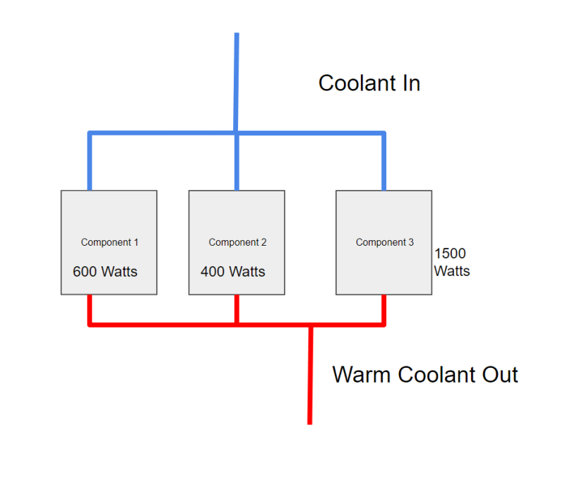
I am working on sizing the thermal system which cools down 3 components which are enclosed in the same housing. The coolant enters the housing and then splits into 3 branches to take away from the 3 components separately. Once the coolant flows through those 3 components, both branches combines into one branch and the warm coolant then goes into a heat exchanger where it transfers heat to the cooling medium before returning back to the components.

The component ratings are:
Component 1 600 watts
Component 2 400 watts
Component 3 1500 watts

So should I size my thermal system to 1500 watts or 2500 watts?

The thermal system delivers the cold liquid to the heat exchanger to take away heat from the warm coolant.
Thermal_r52dqk.png
 
Replies continue below

Recommended for you

The expert video. I have been in meetings with client and our project manager and higher management and the meeting went down just like that, and me being the mech engr expert. Like the video those project managers expect you to convince the client you can do anything. lol.
 
Will there always be all three of them at once?
Do you want to cool them to the same temperature?
If so then the flows will need to be proportional to the heat being removed from each one.
Fist, calculate to sed if you have enough flow to even do this.
You need cold enough inflow an enough flow volume. While still respecting flow velocity limits and associated pressure drops.
Then set up some throttling valves on the outlets of the two smaller ones.
And one throttling valve on the merged outlet. Though this may be optional as you will likely need as much flow as possible.
This way you would be able to balance the flows and not waste overcooling the smaller ones.

= = = = = = = = = = = = = = = = = = = =
P.E. Metallurgy, consulting work welcomed
 
Without knowing the operating practice and hence the worst case thermal load, you can't make a decision.

If it is all three then it's 2500. If only 1+2 or 3 on its own then 1500.

But you need some sort of flow control to get this right.

Remember - More details = better answers
Also: If you get a response it's polite to respond to it.
 
Sometimes all the 3 components will be ON, while other times not some will be active. There is a pump to circulate the coolant to maintain the required flow rate. All these components have the same operating temperature range.
What factors/thermodynamic equations to be considered to determine the flow rate in the worst case scenario i.e. all are working at their rated capacity?

 
Well, Component 3 has 3.75 times the heat rejection as Component 2.

As a first reasonableness check, if the red fluid is the same temperature at both inlets, and the desired component temperature is the same, what do you think the flow necessary for Component 2 relative to Component 3 would be?

Do you really need the extra level of isolation described in your first post?
 
Ed Stainless hit it right. Are the loads concurrent or non concurrent? and about the weather conditions between summer and winter would it impact the performance of the thermal system?
 
I would treat this as a chilled water system and use primary-secondary pumping. Have a pump for each item to be cooled, thermostatically controlled. The whole system should be at least equal to the entire load + a safety factor to account for fouling. That way, If a pump comes on, the other systems will not be affected. The total flow would be served by a single pump + backup.
 
There are thermally activated valves that you can put on the outlets that will adjust based on temperature.
You would need to install a small bypass around them you assure that the flow never went to zero.


= = = = = = = = = = = = = = = = = = = =
P.E. Metallurgy, consulting work welcomed
 
Without a physical model of the surface over which this heat is to be removed from each of these components, its not possible to tell what flowrate of coolant is required for each unit. It depends on the surface area presented for heat transfer, the nature of this surface ( plain smooth or some other uneven surface??) and the velocity of coolant through the coolant flow channel in each unit. There may be some limitations imposed by the coolant also depending on the temp at which this heat is being removed.

Q = U. A. LMTD - see your heat transfer text book.
 
Status
Not open for further replies.
Back
Top