Continue to Site

Eng-Tips is the largest engineering community on the Internet

Intelligent Work Forums for Engineering Professionals

  • Congratulations KootK on being selected by the Eng-Tips community for having the most helpful posts in the forums last week. Way to Go!

How to use CIN3D8 elements in ABAQUS for infinite boundaries?

Status
Not open for further replies.

anthaivn2019

Structural
Jul 4, 2019
19
Dear all,
This is the file I created it for the error. "Infinite elements must share a complete face with one and only one other non-infinite element. The elements in element set ErrElemInfiniteAdjacency are not properly connected."
Can you help me know this error?

Many thank you.
 
 https://files.engineering.com/getfile.aspx?folder=d5a59e2d-5cb3-4817-a0fd-e909e85e05ca&file=SOLID-5.inp
Replies continue below

Recommended for you

I never had really good success when using infinite elements except of very simple cases. So good luck because they are tricky to use initially until one understands them.

The only thing I can suggest is to look on the help manual section 25.3.1 about infinite elements.

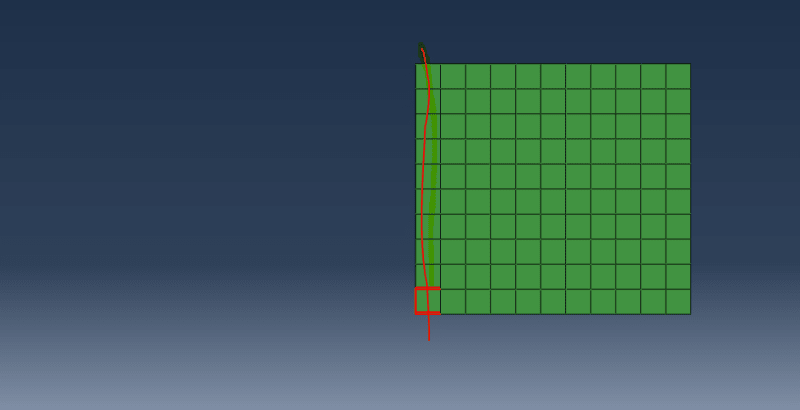
I think in your model you only need one layer of infinite elements not many. Thus use only one layer next to the C3D8R elements. So basically if you look in help infinite elements are not suppose to be connected to each other along the 'infinite' direction

See the attached which marks the infinite elements (just one slice), the rest has been deleted. Also look in the help to see how long to make the element along the 'infinite direction' - not sure if square is ideal.
Search the below in the help manual for an abaqus benchmark with inf. el.
2.2.1 Wave propagation in an infinite medium

Capture_lkic5y.png


Also this post is good, but that might be you posting it :)

See there the meshes how the infinite element mesh is!
 
Apart from the fact that you should use only one layer of infinite elements, you must also make sure that their node numbering is correct. It should be such that the first face of each of these elements is connected with finite elements. In your case the direction was opposite (infinite direction pointing towards finite elements instead of far field). To change this I:
- deleted all infinite elements apart from one layer (Edit Mesh —> Element —> Delete)
- created geometry from all elements’ faces (Geometry Edit —> Face —> From element faces)
- made a partition of unit thickness to assign these infinite elements’ layer again
- assigned two separate solid sections to these 2 cells
- meshed thick region with finite elements and thin one with acoustic elements (important: for this thin layer region I used sweep meshing in the direction opposite to thick cell to make sure the infinite elements will have proper direction)
- generated input file
- changed acoustic elements to infinite ones

The analysis runs now.
 
This example is 1D say found in wave propagation, the mesh is very coarse (L = wavelength/10), and is not going to capture the wave if you are looking at that. Also the time step in explicit and wave prop., is typically dt = 0.9*(Elementsize_smallest/Cspeed_long_wave). Finally one needs to output with a sampling freq. which is higher then the freq. content of the wave.

Some time ago I did a small 1D benchmark in ansys using infinite elements for absorbing Lamb Waves (S0 mode) in plates, and that worked fine. It is a an easy one to start with.
See here for more details:

For a more complex benchmark where there are many more waves prop. (not only S0) making it more difficult to dampen them (for an infinite element or dashpots).

see Abaqus help:
2.2.1 Wave propagation in an infinite medium
 
dear all,
Thank you very much if you give me the .cae file or filming for reference.

 
In the previous post I forgot to mention some important steps that I’ve taken to fix this issue. So after the first step you should change this one layer of infinite elements into finite elements (like C3D8) in the Mesh module (Assign Element Type). Also after you create geometry from elements’ faces don’t forget to delete underlying orphan mesh and use Shape —> Solid —> From Shell on all faces. Otherwise you would have to mesh shell geometry.

If you want I can attach .inp file with working analysis.
 
Dear Cách FEA ,
Can you please send me the .inp file.

thank you.
 
Status
Not open for further replies.

Part and Inventory Search

Sponsor