anthaivn2019
Structural
- Jul 4, 2019
- 19
Dear all,
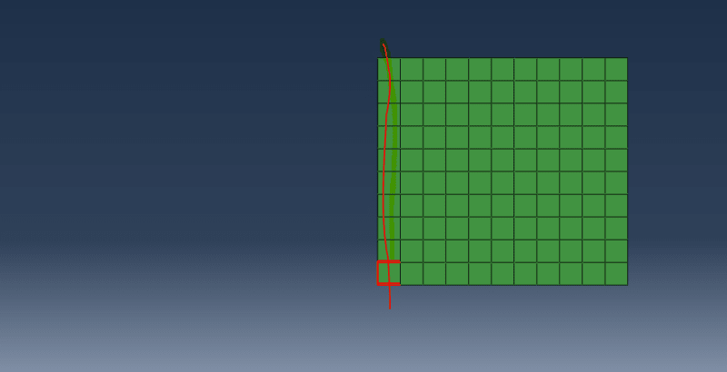
This is the file I created it for the error. "Infinite elements must share a complete face with one and only one other non-infinite element. The elements in element set ErrElemInfiniteAdjacency are not properly connected."
Can you help me know this error?
Many thank you.
This is the file I created it for the error. "Infinite elements must share a complete face with one and only one other non-infinite element. The elements in element set ErrElemInfiniteAdjacency are not properly connected."
Can you help me know this error?
Many thank you.
")