Continue to Site

Eng-Tips is the largest engineering community on the Internet

Intelligent Work Forums for Engineering Professionals

  • Congratulations KootK on being selected by the Eng-Tips community for having the most helpful posts in the forums last week. Way to Go!

How you read this drawing?

Status
Not open for further replies.

Kedu

Mechanical
May 9, 2017
193
I've always been under the impression that if the drawing creator missplaced the datum feature symbol for a cylindrical surface, the datum is still the axis (yes, even the datum feature symbol is not aligned with the size dimensions, AGAIN, on a cylindrical feature and not on a width/ tab).

Anyone else seeing this otherwise?
I will learn from anyone.

Again, as I stated before, for me if someone misplaced the datum FEATURE SYMBOL on a cylindrical surface (not on a width or tab) I will interpret it just as I stated, A MISSPLACEMENT and NOT that the datum is now a plane (or a line) instead of the axis.

opposite opinions are welcomed and encouraged.
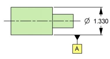
DTP_-_Copy_ysunrn.jpg
 
Replies continue below

Recommended for you

Sure, why not. I agree to make you happy. I'd personally demand the drawing be fixed or just ignore the drawing because the rest of it is likely also just "misplaced."
 
Maybe I haven't wasted enough of my life playing junior GDT prosecutor. The intent is clear. I'd skip right past this without a hangup. The datum is the feature, not the dimension.

That said, what am I missing? What is the requirement?
 
The question is a quite simple:
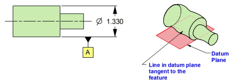
Could shown callout be interpreted as datum target line or plane?
Or otherwise stated, would you read the print this way, as datum target line or plane and not datum axis?

Still think the answers of my above questions are: NO
 
I agree with not worrying about it. The chance of misinterpretation is very small; "the datum of a cylindrical datum feature is the axis of the datum feature simulator."

edit: If the diameter symbol were missing from the related dimension, there could be problems.

"Know the rules well, so you can break them effectively."
-Dalai Lama XIV
 
Is there some reason the Y14.5 Committee specified they be exactly aligned that is actually wrong? I was never a fan of the toilet plunger and they should have retained the position directly as part of the identifying dimension, but here we are, excusing sloppy work because "we" know what it means.
 
Kedu,

I don't see a problem here. You specified a diameter, and you applied a datum to it. I am searching through ASME Y14.5[‑]2009 here, and their datum boxes are applied to the diameter's FCF, to the diameter itself or lined up to the diameter arrow. It is clear to me that your [⌀]1.330"[ ]diameter is the datum feature.

On a drawing, I may move the datum box to clear other views on the drawing.

Your terminology makes me nervous. Your datum as shown is not the centre line. The centre line is imaginary. The datum is the centre of your [⌀]1.330"[ ]diameter. That other diameter has its own centre, which is nominally the same as that of the big diameter, but will in practice be slightly off.

--
JHG
 
Kedu,

Doing it your way is not explicitly forbidden, but if you "ask" the standard how to do it, the "answer" will be:

The datum feature symbol is applied … as follows:
(a) placed on the outline of a feature surface, on an extension line of the feature outline, clearly separated from the dimension line, when the datum feature is the surface itself
(b) placed on the dimension line or an extension of the dimension line of a feature of size when the datum is an axis or center plane.

This is from Para. 3.3.1 2009 version. I am sure both older and newer version(s) are not much different.

"For every expert there is an equal and opposite expert"
Arthur C. Clarke Profiles of the future

 
Hi all,

In the drawing posted by OP (which is a new tip from Tec-Ease), the datum is apparently the tangent plane (based on ASME Y14.5M-1994, Y14.5-2009, and Y14.5-2018). I do not understand why the datum is not the axis of the cylinder, which is the datum feature. Can someone please explain? Thank you.

1_j8y1hq.png
 
Tec-Ease answered and admitted that their choice of using cylindrical feature (to get the point they were after) was not the best.
They should have been using a width or tab to make it clear and less ambiguous.
 
Kedu,

Their choice may not be the best. However, what I am trying to find out is whether their tip/interpretation is correct or not.
 
Checkerhater quoted the standard:

"...placed on the outline of a feature surface, on an extension line of the feature outline, clearly separated from the dimension line, when the datum feature is the surface itself."

Since the given symbol is not aligned with a FOS dimension, then apparently the "datum feature is the surface itself." That means that the datum feature is the cylindrical surface of the OP's part. Well, for a datum feature that's a cylindrical surface, guess what the datum is? The axis!

I agree with Tarator. There's no confusion, even if we go by the Y14.5 definitions.


John-Paul Belanger
Certified Sr. GD&T Professional
Geometric Learning Systems
 
Ok - if I really wanted to use the tangent plane then I have to use a note? But we know that when it's a plane it's only the highest points of the surface and not the lumpiness of the actual surface. Seems confusing.

What if the same line was an extension on the small diameter of a torus? Is it a plane or is it the entire toroid surface?

What if it's the tangent to a sphere? Is it the plane or the entire sphere?
 
From the tec-ease tip pertaining to the above feature "In the view below, because the datum target feature is offset from the size dimension line, the datum may be interpreted as a line lying in a plane tangent to the feature indicated."

It doesn't say that is the correct interpretation, rather that it is a possible interpretation. I think 99% of the time one can assume the intent is to designate the entire diameter/axis NOT the tangent plane/derived line contact, however why leave the room for interpretation? The standard lays out and depicts several methods for acceptable datum feature symbol application to a cylindrical FOS, this is not one of them (though a somewhat generous reading of the text could possibly be interpreted to allow it).

I agree with 3DDave, I would personally request it be changed. I don't think we can say that the intent is 100% unambiguous.
 
Tarator said:
However, what I am trying to find out is whether their tip/interpretation is correct or not.

It is hard to disagree with such authority, but IMHO I think they are just plain out wrong. There is no support from the standard for such explanation of datum plane and a line in the datum plane

 
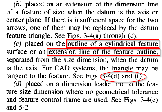
Y14.5-2018 seems to directly support the idea that the OP's picture is a legal way of creating a datum axis. According to 6.3.2.1(a), the datum feature symbol may be "placed on the outline of a cylindrical feature surface or an extension line of the feature outline, separated from the size dimension, when the datum is an axis." (My emphasis.)

So it's not a misplacement. And there's no tangent plane idea here.

EDIT: I see a cylinder as having two outlines -- circular view and lengthwise view. So when they say "outline of a cylindrical feature surface," that seems to allow for the lengthwise view being tagged as a datum feature, even separated from the size dimension.
 
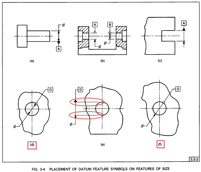
The same text quoted by Belanger above appears also in the 2009 version of the standard, paragraph 3.3.2 (c). However, it points to illustrations that only show the circular outline being utilized for connecting the datum feature symbol. But I agree that the text itself does not specify that only the circular outline is relevant for this option of placement.
 
They are really quite specific in the limited array of acceptable depictions in 2009. People should use Fig. 3-4(c) more just for the irritation factor.

Note :

(b) placed on the dimension line or an extension of the dimension line of a feature of size when the datum is an axis or center plane.

So, if you want the axis, align it with the dimension line unless it shows the circle, then proceed as in (c).

"Separated" clearly means that the datum feature symbol is not co-located with the dimension as it was for the first 40 years of the Y14.5 standards, not that the alignment required for cases such as (b) only applies when it suits the drafter.
 
Regardless of placement of datum feature symbol issue and discussions, don't you find the idea of "datum plane" and "line in datum plane tangent to the feature" a little disturbing?
Where that idea is coming from? It's something I've never heard before.

 
Belanger,

That description from Y14.5-2018, 6.3.2.1(e) has existed since 1994. See below from 1994, 3.3.2 (c) and Fig 3-4.
My interpretation of the "outline" would be the circular one as 3.3.2 (c) refers to Fig 3-4 (d) and (f). And the "extension line" of the feature outline would be something like the extension lines shown in Fig 3-4 (e). Though 3.3.2 (c) does not refer to it. 3.3.2 (d) calls out Fig 3-4 (e) but it seems mismatching.

Y14.5-1994_3.3.2_bbyszr.png

Y14.5-1994_Fig3-4_dhkl99.png
 
Status
Not open for further replies.

Part and Inventory Search

Sponsor