michaeljack88
Civil/Environmental
- Jul 10, 2024
- 8
I'm reviewing a modification to a multi-intake hydro power scheme and have attempted to do some check calculations myself which aren't working out.
Summary
[ul]
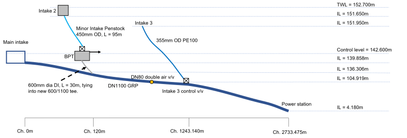
[li]There is a main intake which feeds a penstock to the power station.[/li]
[li]Two secondary intakes discharge water into the penstock.[/li]
[li]The second intake has presented air entrainment issues which need to be resolved with the preferred solution being constructing a break pressure tank (BPT) on the second intake pipeline with a top water level the same as the main intake chamber.[/li]
[li]The secondary intakes discharge the flow into the penstock via a 90deg tee.[/li]
[li]There is a control valve on entry to the BPT to throttle the flow to no more than 0.65 m3/s which is a maximum flow available, the normal flow is around 0.412 m3/s.[/li]
[li]There is a spillway on the side of the BPT to discharge the flow when the scheme is off.[/li]
[li]The pipe material in the main penstock is GRP and the secondary pipelines plastic with a ductile iron section between the BPT and the penstock
[/ul]
Challenge
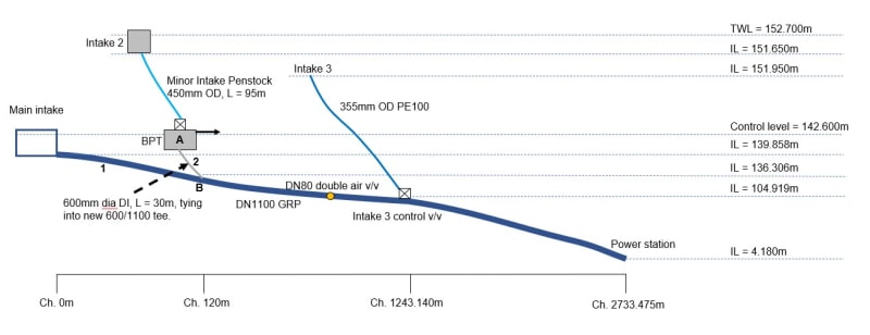
[li]The head loss in the pipe between the BPT and connection to the penstock should presumably be less than the head loss between the main intake and where the second intake connects to the penstock.[/li]
[li]The total flow required at the power station is 1.74m3/s.[/li]
[li]The flow's should be split as follows; 1.2 m3/s from the main intake, 0.412 m3/s from the second intake and 0.122 m3/s from the third intake.[/li]
Method
[ul]
[li]The Colebrook-White/Darcy's equation has been used to calculate the velocity (V) in the pipe between the BPT and the connection to the penstock.[/li]
[li]Point B (where the pipe from the BPT connects to the penstock) has been modelled by subtracting the headloss of the pipe between the main intake and where the second intake connects to the penstock. I think this is where the issue lies. When I run the calculations the headloss of the pipe between the BPT and the connection to the penstock is higher than the pipe between the main intake and where the second intake connects to the penstock.[/li]
[/ul]
If anyone has any pointers on direction that would be much appreciated.


