Continue to Site

Eng-Tips is the largest engineering community on the Internet

Intelligent Work Forums for Engineering Professionals

  • Congratulations KootK on being selected by the Eng-Tips community for having the most helpful posts in the forums last week. Way to Go!

Hydraulic Design - Break Pressure Tank 1

Status
Not open for further replies.

michaeljack88

Civil/Environmental
Jul 10, 2024
8
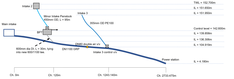
I'm reviewing a modification to a multi-intake hydro power scheme and have attempted to do some check calculations myself which aren't working out.

Summary
[ul]
[li]There is a main intake which feeds a penstock to the power station.[/li]
[li]Two secondary intakes discharge water into the penstock.[/li]
[li]The second intake has presented air entrainment issues which need to be resolved with the preferred solution being constructing a break pressure tank (BPT) on the second intake pipeline with a top water level the same as the main intake chamber.[/li]
[li]The secondary intakes discharge the flow into the penstock via a 90deg tee.[/li]
[li]There is a control valve on entry to the BPT to throttle the flow to no more than 0.65 m3/s which is a maximum flow available, the normal flow is around 0.412 m3/s.[/li]
[li]There is a spillway on the side of the BPT to discharge the flow when the scheme is off.[/li]
[li]The pipe material in the main penstock is GRP and the secondary pipelines plastic with a ductile iron section between the BPT and the penstock
[/ul]

Challenge
[li]The head loss in the pipe between the BPT and connection to the penstock should presumably be less than the head loss between the main intake and where the second intake connects to the penstock.[/li]
[li]The total flow required at the power station is 1.74m3/s.[/li]
[li]The flow's should be split as follows; 1.2 m3/s from the main intake, 0.412 m3/s from the second intake and 0.122 m3/s from the third intake.[/li]

Method
[ul]
[li]The Colebrook-White/Darcy's equation has been used to calculate the velocity (V) in the pipe between the BPT and the connection to the penstock.[/li]
[li]Point B (where the pipe from the BPT connects to the penstock) has been modelled by subtracting the headloss of the pipe between the main intake and where the second intake connects to the penstock. I think this is where the issue lies. When I run the calculations the headloss of the pipe between the BPT and the connection to the penstock is higher than the pipe between the main intake and where the second intake connects to the penstock.[/li]
[/ul]

If anyone has any pointers on direction that would be much appreciated.

Schematic_Diagram_zsfnr4.png
 
Replies continue below

Recommended for you

Your pipe is too small for the flow you're trying to flow.

Also you say 0.413 m3/ sec in one place but 0.65 m3/ sec in another.

Pressure drop for the same flow varies by (D1/ d2)^4. So your 1100 pipe even with three times the flow and longer, will have a much lower pressure drop than your 600 line.

The system will equalise as the pressure at the tee will be the same in both lines, but your flow will probably be half?

My guess is you need at least DN 900/ 36" or 750/ 30" as a min.

Remember - More details = better answers
Also: If you get a response it's polite to respond to it.
 
That's exactly what I thought, the pipe is too small. I've even tried modelling with a smoother pipe material but that doesn't help.

The normal flow is 0.413m3/s, sometimes it might increase to 0.65m3/s but unlikely.

I also think the short length of pipe, 30m, doesn't help but this can't change unless the BPT moves uphill which I'm not sure is a good idea.

Thanks.
 
If I have read your specification correctly the envisaged solution should work well. Let me give my results in some detail so that you can compare them with your results. You say that you found the pressure drop from the BPT to the penstock to be higher than in the main inlet. I found this to be true for the flow of 0.65 m3/s but not for the normal flow rate of 0.412 m3/s.

Over the first 120 m of the main line with a flow of 1.2 m3/s, roughness of 0.02 mm and ID of 1100 mm I get a velocity of 1.3 m/s and a friction loss of 0.1 metre water. The change in elevation over this section seems to be 0.5 m so there shouldn't be any problem there. To get a flow of 0.65 m3/s in the 600 mm secondary line would require a friction loss of 0.16 mH2O and there appears to be plenty of scope to mount the BPT to provide this head. With the secondary intake being so high the inlet regulating valve will be necessary to limit the secondary flow in my opinion.

To allow the air to de-entrain in the BPT you should use a diameter of around 1200 mm for the BPT.

Can you provide more detail on why you believe the secondary line is too small.

Katmar Software - AioFlo Pipe Hydraulics

"An undefined problem has an infinite number of solutions"
 
Katmar, the way I read it is that both the main intake and the BPT have the same water level 142.6. They clearly join at the same level so all hydrostatic issues are equal. So it just comes down to pressure drop accross 120m of 1100 GRP, which is probably about 3-4 microns roughness? versus 30m of 600mm Ductile Iron, with roughness maybe 50 micron?

The OP didn't indicate that there was any potential to increase the water level in the BPT, but that would seem to solve the issue for sure and not need to be that much more (60 mm?). Even allowing for losses in the tee it would seem to be in the order of 0.1 m.?? Why can't that be done?

Remember - More details = better answers
Also: If you get a response it's polite to respond to it.
 
LittleInch, I had not picked up that the top of the BPT was the same as the main intake. It should be OK, but it would be relatively easy to make the BPT a metre or two taller.

A potential problem not mentioned by the OP is that the outlet of the BPT must be kept flooded at all times so that it does not draw more air into the system. It will be necessary to have some sort of U-seal at the base of the tank and to have a syphon break after the seal. This looks to be one of those designs that is simple in principle but where it would be quite possible to go wrong in the details.

Katmar Software - AioFlo Pipe Hydraulics

"An undefined problem has an infinite number of solutions"
 
Hi,

Thanks for the responses so far, very helpful.

I've attached my workings in Excel which should hopefully be easy and quick to follow.

Point B (where the pipe from the BPT connects to the penstock) has been modelled by subtracting the headloss of the pipe between the main intake and where the second intake connects to the penstock. Point A is the BPT TWL. I think Point B is where the issue lies. When I run the calculations the headloss of the pipe between the BPT and the connection to the penstock is higher than the pipe between the main intake and where the second intake connects to the penstock, the result in this case means that Point B is higher than Point A when minor losses are included.
 
 https://files.engineering.com/getfile.aspx?folder=2deb2840-9e58-4d71-9d1d-cdff5e73a986&file=Calculations.xlsx
Looks to me in cell B83 you have the wrong formula.

To calculate your height you should have point B PLUS the headloss you've calculated.

The formula at the moment (B47-B77) sets point B relative to point A.

I think this should be B49 + B77 ??

Remember - More details = better answers
Also: If you get a response it's polite to respond to it.
 
Thanks, that certainly makes the flow rate look good. I'm curious as to why this is added to Point A? As it's a headloss I had thought it would be subtracted from Point A.

The method you suggest shows that the BPT should be at a higher elevation than initially thought to provide the flow into the system required which isn't surprising.
 
You are starting your analysis from the wrong end of the pipe. You must start the analysis from the point of known pressure which should be the inlet to the turbine. You have stated that the turbine requires 1.74 m3/s flowrate but you have not stated the pressure required at the turbine inlet to achieve this flow.

The pressure drop through the main line to the turbine is insignificant relative to the head available. The friction loss through 2734 m of 1100 mm ID pipe with a roughness of 1 mm is only 8.3 m of water head. So if it weren't for the pressure required to drive the water through the turbine the water level in the main feed line would be less than 13 m. IMO the chances of the water level settling out in the top metre or 2 of the main pipe are very slim (and controlling it so close to the top is potentially dangerous).

You have stated that there are air entrainment issues with the second intake. How do you know the air is coming from this intake? The velocity in the 1100 pipe with a flow of 1.74 m3/s is 1.83 m/s and this gives a Froude Number of 0.56 which would be more than enough to carry any entrained air into the turbine. In fact it is highly likely that there is entrainment happening in the main line anyway, regardless of whether air is being drawn in from the second intake or not.

Even the first section of the main with the flowrate of 1.2 m3/s and velocity of 1.3 m/s would likely cause air entrainment so your air could be coming from several sources.

So your first task is to determine the water level in the main feed line and then you can analyze what is happening at the mixing points.

Some information on how the flowrate through the turbine is calculated would help us to understand the situation better.

Katmar Software - AioFlo Pipe Hydraulics

"An undefined problem has an infinite number of solutions"
 
You are correct regarding air entrainment, we do know we will see entrained air from the main intake as the chamber is relatively small considering the stilling time required to allow the air to come out of suspension. We have isolated intake 2 for some time now and there are no air entrainment issues i.e., penstock pressure decay and subsequent decay in power output, when this intake is isolated from the system, therefore, this has placed our focus on putting a solution in place for intake 2 only.

We can run the scheme at full power with the main intake only in-service, the secondary intakes top-up the flow into the system when there is less run-off.

The rated net head of the machine is 133.3m, 1.74m3/s is the rated flow. We have a flow meter at the station.
 
Its not added to Point A, its added to point B (b49) which is the point of common pressure on the two lines.

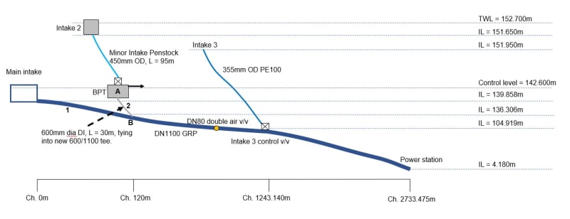
What you're trying to find is what level to set the water level in the BPT. (Which is what I understand point A to be?). it doesn't help that you haven't actually put on the schematic which is point A and which is point B....

So it looks like the level in the BPT ends up some 400mm above the main inlet?

Remember - More details = better answers
Also: If you get a response it's polite to respond to it.
 
Thanks I'll look into this some more, I've now labelled the schematic showing Point A and B, I have also labelled the pipe sections of interest as Point 1 and 2 to aid discussions.

Schematic_Diagram_Labelled.png_ub295p.jpg
 
Ok, so it seems that you are able to control the system to keep point B flooded. It seems very close to the edge to me, but if you are making it work then I can't really argue against it.

If the analysis by LittleInch is correct (and I have not checked it in the detail that they have) and you are not finding that the BPT is overflowing then the pressure drops must be compatible. The question then becomes "how is air passing through the BPT?". If the outlet from the BPT is flooded how is the air getting into the 600 mm section? What are the dimensions of the BPT and what measures have you taken to keep the outlet flooded?

Katmar Software - AioFlo Pipe Hydraulics

"An undefined problem has an infinite number of solutions"
 
Katmar,

My understanding is that the BPT is a new break tank to allow air being entrained in the section from Intake 2 ( only a 450mm pipe) to the new break tank is able to vent off and hence deliver single phase water to the power station.


Remember - More details = better answers
Also: If you get a response it's polite to respond to it.
 
Once I get my numbers in order I'll be happy the pipe size if OK, my impression is that it is but I can't quite get there...yet!

I'm confident that air will not enter the system via the BPT for a few reasons:
[ul]
[li]The geometry (likely something like 5m long x 2m wide x 2 m high) will provide enough volume e.g, minimum 19.5m3 for a conservative 30s stilling time before the water enters the 600 section.[/li]
[li]The submergence on the outlet will be at least 1.5D i.e., 900mm minimum.[/li]
[li]Should the inflow reduce to a situation where the BPT water level reduces then the machine will be shutdown due to lack of water anyway (some checks to be completed here but very confident this is not an issue).[/li]
[li]The BPT overflow will be sized to ensure that it is not drowned to allow air to vent from this location.[/li]
[li]Consideration will be made to installing a vent pipe on the roof of the tank whilst also maintaining suitable freeboard within the tank, the pipe will be over sized e.g., 200mm diameter. The overflow should work but a belt and braces approach will be to include a vent pipe.[/li]
[/ul]

Thanks for the help so far!


LittleInch's understanding of the BPT is correct.

This is a new structure on the pipeline and the pipe after the tank is replaced with a large diameter pipe.
 
I need to read more carefully....

I agree that the proposed dimensions are entirely adequate to allow the air to escape.

Katmar Software - AioFlo Pipe Hydraulics

"An undefined problem has an infinite number of solutions"
 
Status
Not open for further replies.

Part and Inventory Search

Sponsor