Eng-Tips is the largest engineering community on the Internet

Intelligent Work Forums for Engineering Professionals

Hydraulic Grade Line Analysis 1

Status
Not open for further replies.

oilman11

Chemical
Jul 8, 2022
14
0
0
CA
Hi,

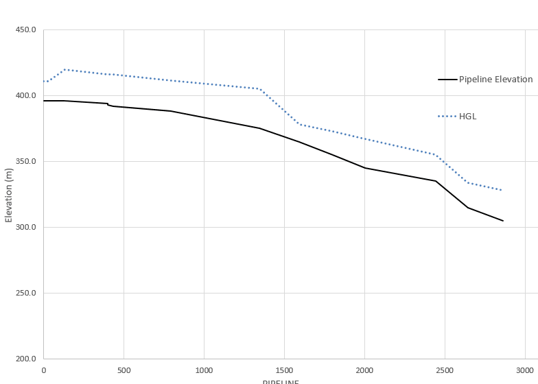
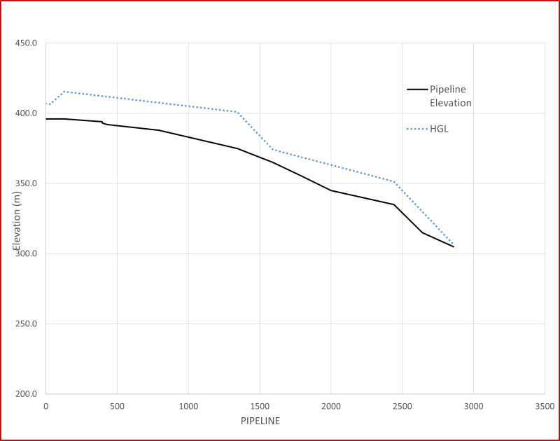
I am looking to figure out where will the flow in the pipeline go from full pipe to slack flow in the attached image?

Background:
The attached image shows a tailings pipeline going down into a tailings pond. The end of the pipeline is at atmospheric pressure. Since the end point of the HGL is at a higher elevation than the end point of the pipeline, it tells me that there is too much energy in the system that will be dissipated by slack flow. My question is, which section of the pipeline would the slack flow be in? How do you figure this out?

Thanks
 
 https://files.engineering.com/getfile.aspx?folder=67a1a0b0-0b8e-4a8a-94c8-5b97ee07db14&file=HGL_Analysis.PNG
Replies continue below

Recommended for you

I'm really not following why the HGL chops and changes all over the place or even why indeed it is higher than the exit point when you've already said it exits at atmospheric pressure.

Ho I normally work it out is to get the profile, then add on the head of the liquid as it enters the pipeline and, for a fixed diameter and fixed flow, draw the hydraulic loss along the pipeline. If this line crosses the profile that's where your slack line starts.

However it needs also to finish at the same elevation as the end of the pipe so if this means that the line crosses the profile but the slope is steeper then you've got the flow rate wrong.

Now when the pipeline stops flowing all the contents of the pipeline will simply drain out of the pipeline and you'll have an interesting time tryin to fill it again.

Here it is for those who can't be bothered to download it.

HGL_Analysis_nbntlh.png


Remember - More details = better answers
Also: If you get a response it's polite to respond to it.
 
The HGL has different slopes because the pipe diameter changes along the way. I have tried making the pipeline diameter smaller in some sections so that it would sort of act like a choke. Yes, the end point of HGL should match the pipeline elevation because it discharging at 1 atm. But...

For this given flowrate, the only way that I can match the HGL endpoint to pipeline elevation is by adding an additional friction drop(either by reducing the pipe diameter or by installing a choking station)or increasing the flowrate. But if I don't do either of that, how would I know where the slack flow is? The pipeline profile and the flowrate cannot be changed and is as shown.

Thanks
 
But how does the HGL increase on the LHS side? That makes no sense to me.

Any the liquid will flow at whatever flowrate it needs to to match the end condition which is where you're going wrong.

As shown your HGL is simply wrong because it implies there is a frictional loss of about 25m at the end of the pipe.

your slack flow would appear to start to occur at either about 1300m or 2450m

But how about you give us all the information you've got in flowrate, pipe sizes, frictional losses, pump head etc

Remember - More details = better answers
Also: If you get a response it's polite to respond to it.
 
HGL increases on the LHS side because there is a pump there.

Yes, the liquid will flow to match the end condition but if I am controlling the flow at a fixed flowrate, the flow will go to slack conditions to dissipate extra energy.

Are you saying that slack will occurs at those two points because the HGL slope is the steepest there?

I've attached the excel sheet showing all the details. I just want to be able to pinpoint the sections of slack flow so the pipe thickness can be increased in those sections. Maybe you would argue that I don't even need a pump in this case but eliminating the pump isn't an option here (that's the only viable way to control the flowrate in this highly abrasive slurry, no valve will last longer than a month)
 
 https://files.engineering.com/getfile.aspx?folder=9de2a55a-4058-4e51-b526-402822829a21&file=eng_tips.xlsx
OK I'll look tomorrow but the pump is s vertical line up not increasing over 150m....

What type of pump? PD I would assume?

Remember - More details = better answers
Also: If you get a response it's polite to respond to it.
 
Slack flow occurs in a pipeline when the pipeline pressure falls below the vapor pressure of that liquid. So, slack flow is when a pipeline hydraulic grade line passes sufficiently below the pipeline profile to cause the absolute pressure in the fluid to drop below the fluid’s vapor pressure. The fluid then vaporizes which results in the pipeline flowing partially full under the influence of gravity.

If your drawing is correct, it doesn't appear to show a slack flow condition. Also, if you increase the pipeline backpressure, the pipeline will fill and slack flow will not occur.

You also need to evaluate the startup and shutdown scenarios, especially if the pipeline doesn't operate continuously.
 
Bimr, that’s true. There is no condition of vapour pockets in the line. It shows positive pressure throughout the line with no sign of slack.

GDD
Canada
 
Yes, that's true, however the HGL is not accurate as it has a back pressure at the end point which doesn't exist. If you set the HGL at the end point to zero ( end open to atmosphere) then to do get slack flow.

Remember - More details = better answers
Also: If you get a response it's polite to respond to it.
 
Atmospheric end pressure can be maintained at the end point only if the discharged velocity corresponds to that particular indicated pressure drop. In other words, if the velocity of the flow rate leaving the end of the pipeline is exactly v = (2gh)^0.5 where h is the difference between pipeline end pressure as calculated by the HGL and that of atmospheric pressure, then pipeline flow rate can sustain the end condition flow rate and there will be no slack flow. If the velocity calculated from the HGL end condition is less than (2gh)^0.5, then the pipeline cannot sustain the discharge condition flow rate and air will enter the outlet if the outlet is not under water, or if the outlet is under water then the pressure just before discharge will be reduced and that pressure reduction will travel backwards into the pipeline until reaching the point where slack flow begins.
The flow rate in the pipeline will then reduce to make the slack flow rate equal to the discharge flow rate predicted by (2gh)^0.5


Einstein gave the same test to students every year. When asked why he would do something like that, "Because the answers had changed."
 
OK,

All you need to do is extend your 8 inch line at the end all the way to the end.

The pressure from a PD pump will vary automatically as it pumps a constant flow. I just adjusted the discharge pressure to get the end point to reach ground level once I had made the last section all 8 inch and got about 140 KPa / 1.4 bar discharge pressure.

Then it looks like this. The HGL doesn't get close to ground level so once you've filled the pipe all the way, you won't be operating in slack flow. If you don't have a valve at the end to stop it all coming out it will continue to flow after you've turned the pump off until it empties just about all the contents as you have a constant slope down and will just pull a vacuum starting at the start point and then gradually the whole pipeline will be at near vacuum until the last bit starts glugging away....

eng_tips_1_kys6ew.png


Does that work for you?

Remember - More details = better answers
Also: If you get a response it's polite to respond to it.
 
If there is slack flow, the velocity and depth of flow will be constantly changing unless the slope is equal to the gradient's head loss. Unequal velocities between segments will back up or draw down levtels at te end of the upstream pipe.

Einstein gave the same test to students every year. When asked why he would do something like that, "Because the answers had changed."
 
Wait a minute. The thick line is the elevation profile of the pipeline. Correct?
If so, we need the pump to push the fluid up-to the star point (0,0). The rest it can flow by gravity.

GDD
Canada
 
Yes, but not at the flow he wants it using the pipe he has.

And it would be slack flow.

Remember - More details = better answers
Also: If you get a response it's polite to respond to it.
 
Status
Not open for further replies.
Back
Top