Eng-Tips is the largest engineering community on the Internet

Intelligent Work Forums for Engineering Professionals

Inlet Geometry 2

Status
Not open for further replies.

TugboatEng

Marine/Ocean
Nov 1, 2015
11,388
1
36
US
Background: I have an engine that I've received into my fleet that smokes at full power. These engines are essentially new and confirmed to be in good operating condition by the manufacturer. Everybody else's stumped so I get to take my turn at it.

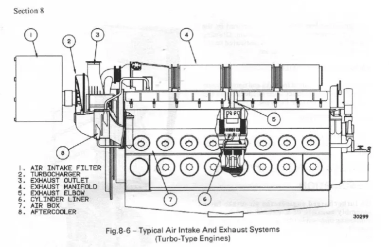
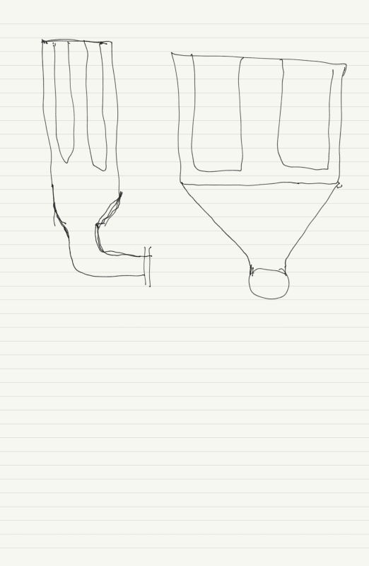
What I have found is that the engine is installed very close to the after bulkhead of the engine room and the air filter box was modified to fit in this space. During the modification, the radiused inlet to the turbocharger was removed to space constraints. It is my belief that the squared off entry is choking the turbocharger for air.

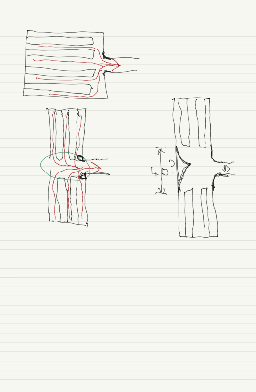
Now I need to figure out how to correct this issue with limited space. I thought about projecting the inlet pipe into the air box and flaring the end of it. Much like a velocity stack on an old carburetor.

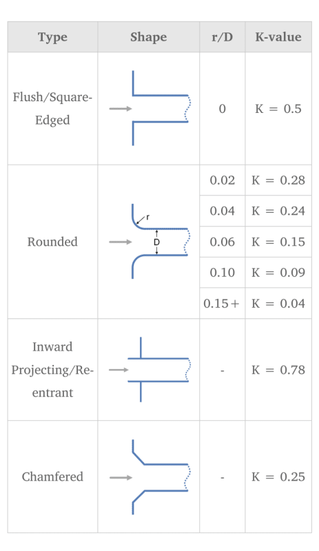
However, this reentrant geometry may also provide the worst k factor.

Screenshot_20231218-142107_nzl2ni.png
 
Replies continue below

Recommended for you

Do you have any instrumentation with you? I'm thinking two or three low-range pressure transducers and something to read them with (Picoscope or similar). Then, of course, you would have data for this engine, and would want to take similar data from the more normal installations...
 
To answer some questions:

-The air filter housing was supplied by the engine manufacturer with 4 filter elements side by side with a straight through configuration. The installer cut the supplied housing in half down the centerline and butted the two halves together, and installed the outlet in the side to make a Tee shape.

-The engine room previously had 16 cylinder 645 series roots blown engines, they were replaced with 8 cylinder 710 series turbocharged engines. The horsepower is the same but I suspect the air demand slightly higher in the current configuration.

-Same story on the exhaust stacks. They were of sufficient diameter for the previous engines of same rating. These engines were designed as drop in replacements for 12 cylinder turbo and 16 roots blown engines. 22-24 inches diameter is correct for this, I should double check.

-It is a combination gear and turbine driven units. There is an overrunning clutch and the turbine is able to overrun the gear drive when power is sufficient.

-The lagging, these turbos are oil cooled. There is a soak back pump to keep the center housing cool when the engine is stopped.


My next steps:

-Take a pitot tube measurement of turbo inlet pressure. Calculate filter differential.

-Measure engine room pressure.

-Block off one side of housing with plywood to test for improvement.

After reading recommendations, it sounds like by best solution is to build a duct perpendicular turbo inlet. Place duct outlet with radiused edges in side of duct so that it is 2*D from any side (16 inches minimum duct size). Install air filter box so that it faces centerline of vessel. If space does not allow I may require a U bend and place it parallel to engine.
 
LI, about engine room air pressure, the turbo engine allows 6inH2O depression while the Roots blown that these engines replaced allow more than double at 15 inH2O.

Air intake volume for a 16 cylinder 645 roots blown engine is 6750 cfm. I suspect the 8-710 turbo engine is closer to 8000 cfm.

Screenshot_20231220-120100_ip62t2.png


Screenshot_20231220-121327_oeinzp.png


Screenshot_20231220-121421_vxzwtt.png
 
Abstract on the turbocharger from Wiki on the 710 series engines:

"Unlike the 567 or 645, which could use either Roots blowers or a turbocharger, the 710 engine is only offered with turbocharging. The turbocharger is gear-driven and has a centrifugal clutch that allows it to act as a centrifugal blower at low engine speeds (when exhaust gas flow and temperature alone are insufficient to drive the turbine) and a purely exhaust-driven turbocharger at higher speeds. The turbocharger can revert to acting as a supercharger during demands for large increases in engine output power. While more expensive to maintain than Roots blowers, EMD claims that this design allows "significantly" reduced fuel consumption and emissions, improved high-altitude performance, and even up to a 50 percent increase in maximum rated horsepower over Roots-blown engines for the same engine displacement. But, unlike the earlier 645 and 567, which could use either turbochargers or Roots blowers, EMD's clutched turbocharger is an integral part of most 710 models."

So does this turbocharger have a turbocharger bypass on the the exhaust gas side ? Could this bypass damper be only partly closed when at full load( when it should be fully closed) ? Symptom of this would be a lower than expected air pressure to the engine when at full load.
 
No bypass. These engines size the turbine for full power operation and use the gear drive to drive the compressor at the low end for best response at all speeds.
 
I have asked if the filters were removed to test and everyone responds yes. I need to clarify if that means the bags or the filter housing. I doubt it means the latter. Do consider that 4 bags in an inline housing is the standard configuration for the engine. I believe the problem is in the geometry of the duct so even removing the filters isn't going to show improvement. I will try blocking off one side to eliminate any effects related to the T configuration.
 
Tug,

Not sure what thats going to show?
Removing the filters will allow a completely differently Air flow which just shows maybe airflow is your issue but not sustainable.
If your going to block off one side I assume this is without filters?
Again, not sure what you're going to determine from that?

You know more about large diesels than I do for sure, but has the fuel side been checked?

Air flow and air pressure in the Chambers checked or can it be measured?

The Air filter I assume is as below in the sketch with 4 in line. Redlines is Air flow.

The modification looks a bit basic for sure so the green area is your issue I think.

So maybe one option is to add volume to the middle and maybe a guide vane. And make the curved inlet smooth with the front plate.

Air_inlet_P1_wgte5j.png


Remember - More details = better answers
Also: If you get a response it's polite to respond to it.
 
Get some incense sticks or some big fat Cuban cigars and see what the approach air flow looks like.

--Einstein gave the same test to students every year. When asked why he would do something like that, "Because the answers had changed."
 
That 3rd photo shows a pipe projecting well into this filter housing, but its end is capped off ? How then does air get into this projecting nozzle ?

From that Wiki abstract:
"The turbocharger can revert to acting as a supercharger during demands for large increases in engine output power."

Perhaps it is this mechanism that isnt kicking in at high load ?
 
There are two engines in the boat behaving identically. The engines are relatively new and in good condition. There are no mechanical faults.
 
georgeverghese said:
That 3rd photo shows a pipe projecting well into this filter housing, but its end is capped off ?

The ID of the inward projecting/reentrant is rounded. The radius seems to be about equal to the pipe wall thickness. The angle of the 3rd picture has the viewer looking straight at the rounded entrant. This may give the appearance it is capped.

Good Luck,
Latexman

 
Thanks for that Latexman, that optical illusion got me.

This projecting inlet essentially incapacitates some 2/8 = 1/4 of the total surface area of the 4 filter elements. So, if you keep the feed pressure to the compressor side of the turbocharger the same, air flow must drop to (3/4)^2 = 9/16 = 55% roughly of that for a flush nozzle.
 
Interesting. One of my initial thoughts before looking into this was a "velocity stack" similar to what is used inside of motorcycle airboxes. I see now that my assumptions have misled me.
 
So the question now is whether there is enough space to move that nozzle further back flush with the flat wall. That rubber connection looks quite short and not a lot of spare room??

Also remove that bit of angle above the nozzle and anything else which disrupts the flow inside. I would also add some extra space in that central plenum.

Remember - More details = better answers
Also: If you get a response it's polite to respond to it.
 
Can you involve the engine supplier in performing testing on a shore-side engine where there is room to work? Being able to remove a cover opposite the inlet would allow far better access to installing different options.
 
There is no reason why this filter box needs to be in this cramped space right in front of this turbocharger. It could have been located in some area where there is more room, and have a one size larger filtered air feed pipe routed from the filter box to the turbocharger compressor feed with a few piping elbows. This way, you could have used used the standard filter box configuration.
 
Good idea GV! Being further away can mean more twists and turns. I’d back-calculate the diameter to give less dP than Mnfr’s std. The one diameter RoT may not cut it here. I’d be sure.

Did I read two engines have the same issue? So, would an inlet air header to both make sense?

Good Luck,
Latexman

 
Will need a new box for sure.

Maybe something like this?

Untitled_P1_diell1.png


Remember - More details = better answers
Also: If you get a response it's polite to respond to it.
 
Status
Not open for further replies.
Back
Top