Eng-Tips is the largest engineering community on the Internet

Intelligent Work Forums for Engineering Professionals

Inlet Geometry 2

Status
Not open for further replies.

TugboatEng

Marine/Ocean
Nov 1, 2015
11,388
1
36
US
Background: I have an engine that I've received into my fleet that smokes at full power. These engines are essentially new and confirmed to be in good operating condition by the manufacturer. Everybody else's stumped so I get to take my turn at it.

What I have found is that the engine is installed very close to the after bulkhead of the engine room and the air filter box was modified to fit in this space. During the modification, the radiused inlet to the turbocharger was removed to space constraints. It is my belief that the squared off entry is choking the turbocharger for air.

Now I need to figure out how to correct this issue with limited space. I thought about projecting the inlet pipe into the air box and flaring the end of it. Much like a velocity stack on an old carburetor.

However, this reentrant geometry may also provide the worst k factor.
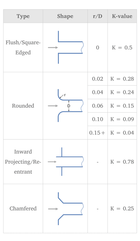
Screenshot_20231218-142107_nzl2ni.png
 
Replies continue below

Recommended for you

TugboatEng said:
I have asked if the filters were removed to test and everyone responds yes. I need to clarify if that means the bags or the filter housing.
Did you get this clarified? If it was only the bags that were removed then removing the entire housing will immediately tell you if the problem is the housing modification.

Katmar Software - AioFlo Pipe Hydraulics

"An undefined problem has an infinite number of solutions"
 
I think that LI is on the right track.
The outlet of the filter box should be a radiused rectangle that is full height of the filter box and width equal to your intake diameter.
Any radius at the transitions would help, even a small one.
Then this 'intermediate plenum' can taper down you your correct intake size.

= = = = = = = = = = = = = = = = = = = =
P.E. Metallurgy, consulting work welcomed
 
This merging tee flow configuration obviously adds much more dp. Reject this and revert to the standard box configuration at the least, assuming the exit pipe doesnt protrude into the filter box as current. For the remotely located filter box option, would suggest the intermediate piping run take up no more than 10-15% of the design case dp allocated to the filter assembly at full load air flow. Some flex hose in this piping run may be required to isolate the piping and filter box from engine vibration.
 
Honestly, I'm not totally sure what engine series it is. We acquired a company that was operating this vessel. This engine comes from the middle of the Caterpillar takeover. It's an EPA Tier 3 certified package that was installed around 2018 or 2019. All of my information is second hand but the previous company had been chasing this problem with the supplier and got nowhere. It's out of warranty now and I want to fix the problem. Previously the supplier was chasing injector mapping which they shouldn't be able to change on a certified engine. I walked on the boat and the air intakes immediately caught my eye as suspicious. I appreciate all of the feedback I am getting. I will follow-up but this boat isn't local to me so it may take some time. However, new opacity rules are coming and I may have to correct this by March.
 
You might want to have somebody do a CFD analysis before you go cutting up things.

--Einstein gave the same test to students every year. When asked why he would do something like that, "Because the answers had changed."
 
Can you put a stop on the fuel rack that would keep the fuel rate below the point where smoking starts? Might be a short term fix. There is enough room to install an elbow at the turbine inlet, remote mounting the filter box seems like the most reasonable approach, but watch out for prespin at the turbocharger inlet as that acts just like additional restriction.
 
Status
Not open for further replies.
Back
Top