Continue to Site

Eng-Tips is the largest engineering community on the Internet

Intelligent Work Forums for Engineering Professionals

  • Congratulations KootK on being selected by the Eng-Tips community for having the most helpful posts in the forums last week. Way to Go!

Integrity Reinforcement in Transfer Slabs 9

Status
Not open for further replies.

KutEng

Structural
May 27, 2019
40
Just want to bring back an old post by KootK that got no real answer: Integrity reo has just been introduced into our Australian concrete standards so I don't think many of us will have this figured out yet.

This is a tough one because transfer slabs really benefit from integrity reo since a failure in a transfer slab can be catastrophic, however trying to get adequate integrity reo over your columns seems like a huge ask.

It's almost as if this clause is pushing us away from designing flat plate transfer slabs by making it so unfeasible that no one is willing to use them anymore. Generally, on some of our transfer decks we transfer columns at ground floor that continue up to 15 stories (around 7000kn of load). It would be almost impossible to fit enough reo over your column in these cases.

Would love to hear from some people who have managed to satisfy this clause in a transfer slab, or if its generally left out of transfers.
 
Replies continue below

Recommended for you

Rapt, I understand the American standards explicitly define the reinforcement required in each direction however I still believe ours doesn't.

The clause states "The summation of the area of bottom reinforcement connecting the slab, drop panel, or slab band to the column of column capital on all faces...".
The way I see it if you have all your reo in one direction and none in the other you will still satisfy this clause as your sum of reo area in both directions is greater than As.min.

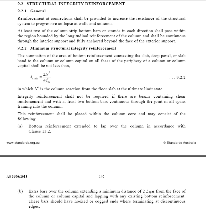
One thing however I did notice was this which complicates things even more for wallumns:

Capture_qd2kk9.png


I guess that eliminates putting all your bars in one direction, however, as KootK mentioned placing at least 2 bars within the longitudinal column reo of a 250mm wide column when there is a 100mm riser dead centre at the end of the column is easier said than done.
 
For reference here is the clause from AS3600

Capture2_phphrk.png
 
Ar Engineer,

That was never the intent. There were interpretation problems in how it was worded in other codes also as to whether the code was applying to the reinforcement in each direction or on each face, and also what to do at edge and corner columns. We tried to avoid the same interpretation problems. Obviously we failed.

And I cannot see where there is any benefit by even trying to put it all in one direction. Can you please explain!

It would be nice and would make code writers jobs a lot easier if engineers would think logically about how a building is acting and detail accordingly!!!!!!!
 
At this point, the slab is doing its level best to collapse so 'thinking logically' is not worthwhile advice as obviously the original thinking wasn't right.

The slab will need to be demolished (or patched with grout if it's a Sydney apartment block) so any load path that hangs the slab up for a few hours is enough. Does the slab retain its awesome capacity for redistribution at this stage? Maybe a one-way load path with integrity bars along the long column edge would be sufficient. A case for full-scale testing if not already done.
 
steveh49,

Sorry, I must be missing something. Where has an existing Sydney apartment block with transfer problems been mentioned in this.

The logic to me would be that the designer consider how much load is coming in on each side of the column. With a transfer slab, there is a good chance that most of the transferred load will come in through one face. So that direction would require more integrity reinforcement.

In this situation, even punching shear calculations probably should recognize the difference, but code formulae cannot or do not indicate this. That is where the "engineering logic" has to come into design. Codes cannot cover every specific situation. Engineers are responsible for a building design, design codes are not. Design Codes give limits and guidance. There are many situations where the designer has to use his engineering understanding to apply the rules logically to his or her situation. Unfortunately many engineers these days expect the design code to do it all for them.
 
I understand this to be a new requirement, not covered by commentary and probably won't be for some time (ie years). So designers are going to have to guess at what the limits are. But this is a fail-safe that is only activated after a failure of the primary load-carrying system. Something has gone wrong by this stage that may also affect the performance of the integrity reinforcement (loading/design/construction/material-supply issue). On top of this, post-failure performance is not a primary learning area for engineers. All of this adds up to a need for more prescription in the code until it is better understood IMO.

Have there been any collapses in Australia that would have been prevented by this integrity reinforcement? If there's no history of it, I can't see people rushing to become experts when there's so much else to do and learn.

Edit: You can just put the reo where it's convenient apparently. A SRIA newsletter says to put it all in one direction if there's a penetration that prevents it in the other direction.
 
AS3600 (clause 2.13 in 2009 and AS1170) and BCA has required that Robustness be checked previously. They have just has not provided any guidance on what should be done. That does not therefore mean that engineers should have been ignoring it. Designers were required to research the requirements for themselves and produce designs that provided adequate robustness.

WE have now provided MINIMUM requirements for slabs at columns. Unfortunately the minimum requirements for Beams have not made it into this version of AS3600. That does not mean it does not have to be checked for beams. Designers are required to check for Robustness in all cases to check if more than the Minimum is required.

And for Transfer Members, they have to decide what to do, especially single span transfer members which cannot be made robust by adding continuous bottom reinforcement to cater for catenary action as that is not an option. Some other solution is required. I tried to get an extra Importance Strength factor added for this but it is still under debate so is not in there.

The comment that

"post-failure performance is not a primary learning area for engineers"

is not an acceptable solution or reason for not doing it. If it is necessary (and it is) then you are required to research it and provide adequate solutions. The next comment will be that recompense is not adequate. You are required to produce designs that are in accordance with BCA and need to charge accordingly to provide designs that meet these requirements.

Same with fatigue.

As I said above, too many designers are treating the code as a Cook Book.

There should be a commentary out early next year.

Where there is a penetration on one face as shown in that diagram, it is pretty obvious that there is no reinforcement required on that face. But I would disagree that it is then treated as one way. It would be similar to an edge column condition.

 
Additional thoughts based on subsequent discussion:

1) In my opinion, a fundamental understanding of how integrity reinforcement is meant to work is necessary precisely so that designers can extend and modify such code provisions rather than just following them rote. In this case, I believe that a fundamental understanding of the mechanics should be steering designers away from an integrity reinforcing layout that would provide equal capacity at each of the participating sides of a column. More on this below.

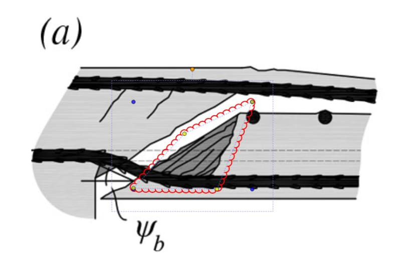
2) As shown below, the name of the game with integrity reinforcing is creating the ability to develop a secondary punching shear frustum further out than the original, inadequate frustum. As such, another set of concrete struts develops just outside of the original failure surface. In order to keep the demands on those struts minimal, it would behoove the designer to distribute integrity reinforcement about the column in proportion to the side lengths rather than simply splitting it equally among the four sides. With this in mind, it would make no sense to me to take a 10" x 48" column and pound half of the integrity steel through the short dimension where, surely, you'll just overload the extended failure frustum. It would be vastly more preferable, I think, to spread that demand about the column as much as possible so that concrete shear stresses remain low. This is one instance where I feel that a 50/50 distribution of integrity steel would be ill advised for a wallumn.

3) For situations that are, effectively, three sided punching shear (edge column / sleeve), not all of the sides will be of equal value when it comes to providing fail safe reliability against ULS punching shear. In my opinion, it is clear that the bars that are able to pass through the column and extend out the other side are of much greater reliability than those that must be dubiously developed within the column. This is a second instance where I feel that a 33%X3 distribution of integrity steel need not be rigorously applied.

4) Codes vary on this a bit but many reference the desire to create the ability to form a rebar net to hold up a slab post-punching shear. That, in addition to the primary mechanism of last ditch punching shear resistance. In this sense, there is some tacit acknowledgement of catenary action. In the Canadian code, one is allowed to "lap" integrity reinforcing with the distributed bottom steel mat to achieve this. As such, it seem more sensible to distribute punching shear reinforcing such that it is lapping with available rebar of a similar, available capacity to itself. For a 10"x48" wallumn, it seems unwise to dump a gaggle of 30 M integrity steel through the short side of a wallumn where it would be lapping with, say, 15M@300 bottom bars. Much better to distribute the integrity bars along the 48" length in hopes that slab reinforcement capacity is of a similar order as the integrity bar capacity. This is a third instance where I feel that a 50/50 distribution of integrity steel would be ill advised for a wallumn.

5) With respect to the appropriateness of standard punching shear provisions to transfer slab situations goes, I agree that designer discretion is required. That said, I believe that:

a) If the slab is stiff enough to convincingly behave as a two way slab, then I think that conventional punching shear provisions would apply and that the eccentricity of load could be handled as it normally is, as a load producing moment on both the punching shear failure frustum and on the supporting column(s).

b) I feel that the design process itself will often steer designers towards the right choice for #5a. If column moments and eccentric punching shear demands prove onerous to deal with, then a designer should either stiffen the slab or start considering one way transfer element design options and the shear transfer mechanisms appropriate to that.


c02_i7inzg.jpg
 
KootK, you mentioned in your first post to this topic that integrity reinf action is different to catenary action, and in your most recent post again implied that catenary action isn't the primary goal. Can you provide the references this is based on? I looked up one of the references given in ACI352 and it's all about catenary action. As such, it's not expected to work in some circumstances such as general overload of the slab (ie all bays overloaded like a crowd rather than local overload).

Aside from the alternative to catenary action, it would be interesting to see whether there have been large-scale tests verifying the performance. The article I read referred to testing of slabs with 4mm reinforcing bar (12.9 sq.mm per bar). Some other tests were mentioned but details not given.
 
steve49 said:
Can you provide the references this is based on?

I'm afraid not really as I don't have any of that stuff easily accessible at the moment. In general:

1) It seems to me that the centenary implications vary from code to code. And I'm not sure how purposeful that variation is.

2) Virtually all codes say that the integrity bars should be continuous. This makes one feel as though that should mean continuous between columns (catenary) but I suspect that main thing is continuous over columns. Not that having both doesn't sound pretty great.

3) With many, modern, irregular slab layouts, running the integrity steel column to column is a nightmare. It messes with the basic bottom mat horrendously in terms of layout and effective depth and, as a result is often best stuffed above the bottom mat which has it getting pretty close to mid-depth rather than "bottom" in many cases.

4) As I mentioned in my previous post, the Canadian code allows lapping with the basic bottom mat (I think), which implies a pseudo-adherence to catenary action. As I believe you intimated, catenary action based on integrity level reinforcing doesn't usually check out. Nice as a bonus, of course, but not enough there-there for primary action.

5) The diagram in my previous post, which I believe to be the latest and greatest on this topic (could be wrong), definitely seems to stress the use of integrity steel primarily as a punching shear fail safe rather than a primarily catenary setup. They don't even mention catenary action. This is the one reference that I can provide. See below.

steve said:
I looked up one of the references given in ACI352 and it's all about catenary action.

Can you direct me to this? I'd love to check it out.

c03_kmdlmn.jpg
 
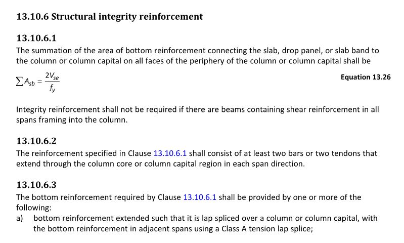
Here's the Canadian version for any interested parties. We were fashionably early to this particular party.

c04_esjqqn.jpg

c05_r6ffpk.jpg
 
Good to see that, once again, our standards are almost a direct copy of the Canadian standards with extra safety factors thrown in to satisfy our conservative quota
 
steveh49,

There are 2 parts to this disussion.

- Robustness rules require that you provide a capacity for the structure to survive the removal of a support. One solution is to provide sufficient continuous reinforcement through the bottom of the support for the member to survive the removal of support by catenary action. Obviously this does not work in single span members or cantilevers hence my comment above regarding single span transfer beams.

- As punching shear is a brittle failure condition, technically we should be providing an alternate load path to that collapse to ensure robustness. In this case the support has not failed, the connection to it has. So again catenary reinforcement will help. But also, in the testing for Studrail back in the late 1980's (I think), it was found that continuous bottom reinforcement through a column slab joint, while it did not increase punching shear capacity as such, it made the failure much more ductile. The collapse load was about 2 - 2.5 times higher. They found this when they compared the effect of continuous rails through the column compared to rails that stopped at the face of the column on the 4 faces. From this, it was decided that continuous bottom rei9nforcement thought the column should be mandatory.

ACI has gone away from this in its latest rules in 2014 ACI I think and allows continuous PT through the column to provide this capacity. While it will provide the caterary action, it does not provide ductility for punching shear. That is why we did not follow the latest ACI318 logic.

And AS3600 is not an exact copy of CSA on this either, but we preferred the total reinforcement logic to the reinforcement per face logic. CSA allows top prestress to be included, even though it is top reinforcement and does not provide this ductility as it has already been used up in the punching strength calculations, though it does contribute to caterary action!
 
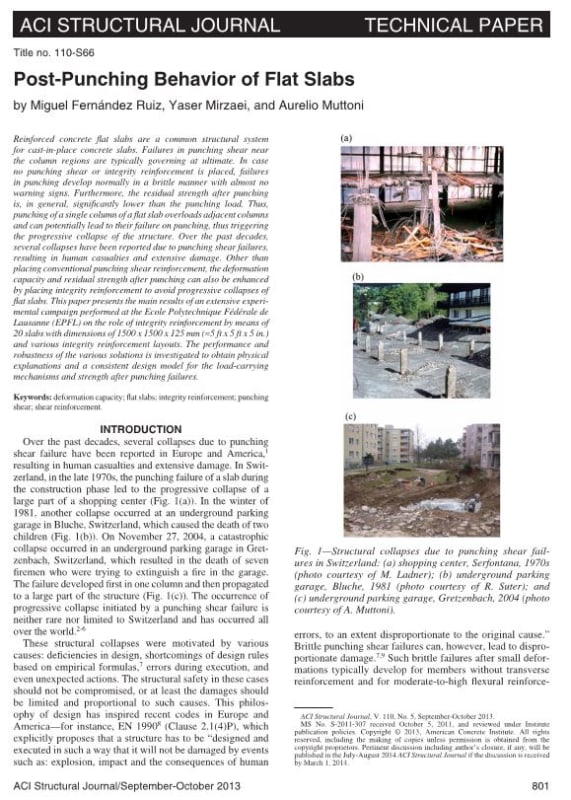
KootK, the article I mentioned is Mitchell & Cook "Preventing progressive collapse of slab structures" Journal of Structural Engineering, 1984. Snippet below. Blink twice if you're happy to receive by email.

Rapt, is the loading for the support-removal case specified? I'd have gone for dead + short-term-live, but perhaps dead plus long-term-live is justifiable. Short-term-live isn't given in any ULS load combinations in AS1170.0.

catenary_ff4tle.png
 
My left eye is twitching up a storm. Mitchel's ours. Very high probability that's the CSA source doc .

 
steveh49,

Logically it would be the Permanent Load case. So SW + SDL + .4LL for normal buildings.

ABCB has put out a handbook on Structural Robustness. It is a free download.

Handbook-Structural-Robustness.pdf
 
Not willing to put this one to bed just yet

Rapt,

The purpose of integrity reo is as a fail-safe in the event of failure so you would expect either miscalculation of design loads, or design loads to be exceeded to cause a failure (assuming perfect execution on the construction end). Wouldn't it then make sense to take your maximum ULS loads when considering integrity reo? Anything less than 1.2G+1.5Q seems like it won't work considering the structure would've been seeing loads around 1.2DL+1.5LL to cause failure in the first place.

I'd assume once the building was evacuated it would be safe to assume DL+0.4LL but by the time that happens, the integrity reo has already failed and you'll be left looking at a bunch of rubble wondering where all that live load went.
 
Ar Engineer,

Integrity Reo N* is defined in AS3600 as the ultimate load. So yes, 1.2D + 1.5Q

We were talking about Robustness (Support Removal) calculations for that case.
 
Where does the difference between removing a support and a support failing come from that allows for a much lower load case to be considered?

I'm not familiar with structural robustness so I may be missing a basic concept here
 
I'm thinking in the case of your support punching you are still providing your loads to that support via your integrity reo and
in the case of removing your support you are providing a new load path to surrounding supports?

Is this correct?
 
Status
Not open for further replies.

Part and Inventory Search

Sponsor