Continue to Site

Eng-Tips is the largest engineering community on the Internet

Intelligent Work Forums for Engineering Professionals

  • Congratulations KootK on being selected by the Eng-Tips community for having the most helpful posts in the forums last week. Way to Go!

internal combustion gas or diesel engine clean sheet designing 7

Status
Not open for further replies.

nanokron

Automotive
May 12, 2019
25
ok I finally have a copy from John Manning’s book, Internal Combustion Engine Design, published by Ricardo, 2012. ISBN 978095732920-1

directly from Ricardo engineering :)


here's a few question that I still not fully understand especially concerning the "Cylinder Block and Cylinder head"

especially from the Sketch DRAWINGS to the Final detail BLUEPRINT DRAWINGS before the first procurement prototype engine

1) when designing an engine "cylinder block" DRAWINGS is there any parts of the engine assembly preliminary design DONE before the said cylinder block DRAFTTING Ex: Crankshaft, camshaft, ect .

2) the designing process of the cylinder block DRAWINGS generally does it start with "Bottom Up design" or "Top Down design".

3) in a cylinder block design preliminary DRAWINGS what are the block Features design DRAFTING sequences Ex: A) crankcase, B) cylinders layout, C) lower cylinder deck, D) water jacket, E) upper cylinder deck .

4) How does the interaction Between the different engineers and the draftsman Works? who will be in charge of the designed features?
of the specific engine part for a cylinder block DRAWINGS

5) at last all the above questions BUT for the "Cylinder Head" part

I am interested in the principle behind engine designing DRAWINGS only, not much in CAD or FEA and or CFD. I am just intrigue by the way they design major engine part like in the 50's, 60's and 70's drafting tables and slide rulers! BUT any computer related design subject still appreciated as a feedback :) casting and machining drawings both are in my field of interest

and if any GOOD publication of concern of the above subject and questions I'll be happy to source if I can get them

engine size mostly of my interest would be bellow 1000 CU-IN or about 17 liters in displacement gas or diesel ICE industrial or automotive from 1 to 8 cylinders either inline or v configuration

any reply appreciated

Steve
 
Replies continue below

Recommended for you

AWESOME! finally I have a basic understanding of the process in sequence. so you rough the model by using a baseline parametric data

of your internal ( rotating, reciprocating with stress analysis, flow dynamics and thermal analysis for the combustion including moving parts ) THAN you build the SHELL around it :0)

SWEET :) now what I have to find is a publication with example of initial baseline parametric ICE concept so I can start from there to fully understand the whole process

and what I need is literature in the 20's all the way to the 70's with baseline parametric ICE concept

all I am interested now is how they parametrically design the first iteration detail drawings of say an old 1950's Waukesha ICE engine as an example that's the info I need to seek now ! not necessarily brand or model specific data

now can you take a say old existing engine design and extract parametric data to conceive another engine variant of that design ( almost reverse engineering in a way )?

Steve
 
nanokron,

Why do you need literature about engines long ago abandoned for superior designs?
 
It wasn't done parametrically if you go back a few decades. The technology to do it, didn't exist back then. 'Course, they didn't have to conform to emission standards back then, and consumer expectations for reliability, durability, etc weren't what they are now.
 
if you take Keith Duckworth who design numerous racing engines for Cosworth I always wonder how he design them. today with all computer technologies and no slide rules or drawing boards, it is a kind of mystery on how they manage to design reliable engines that lasted under tough conditions. I know that many and many prototypes have been tested for the same engine model before success but they still manage to get most everything up to spec and be reliable


one last question is ( the rough initial model design) , is there any mathematical formulas like (feature ratio) you have to apply
before building the initial model in CAD , do you start with a previous existing model or is it done just by experience like making a basic crankshaft with summary of the first agreed sketch ex: engine requirement length is 550mm so crankshaft length would need to be about 530mm for the floating model?

by the way I don't need the newer design because I want to understand the basics of an ICE modeling done on paper and slide rules FIRST like the old timers draftsman use to do, that's the fascinating part to me by doing so, it is way easier to build CAD model afterward!

it is like in electronics you don't design circuits WITHOUT understanding the basic of a resistor or capacitor FIRST

it is the same thing with ICE engines design if you know your proportions THAN you have a real good starting point for your model :)

Steve

 
It wasn't done parametrically if you go back a few decades.

Yes and no. In the sense that 3d CAD wasnt available modern parametric design wasn't, but I would argue that good design has been done parametrically since forever. One of the first things we all should have learned about engineering is basic process starting with listing your knowns and unknowns, once you have the knowns you can start to resolve the unknowns which is the basis of parametric design. In 3d CAD I can constrain the individual components and fill in the block/head between them. Done in 2d that just requires careful drafting of multiple views and a bit of careful consideration/imagination. Paper "motion models" with the max throw of a crank as a dashed circle were common then before we moved into 3d CAD with the same part modeled in multiple positions, and then developed the modern animated models.
 
is there someone here in this thread answering my questions that actually design engine BEFORE the computer age, in slide rules , pencil and paper era ?

just wondering because I am sure that major ICE engine have been design on a monitor screen since the mid 70's at least ?
 
The first time I was involved in engine design was 1992, and it was in the transition from Mylar to a proprietary CAD system. The block for that engine was designed in 1985-1989 and would have been ink or pencil on Mylar, and most of it was hand calculated, by my boss. There may have been some modelling of the combustion forces in that timeframe, there certainly were some balancing programs for crankshafts.

Cheers

Greg Locock


New here? Try reading these, they might help FAQ731-376
 
I should have posted this earlier.


A little humor from the text:

"None of the plain bearing variations was made to run with any success until along about 1940
when somebody who did not know that bronze bearings would not work tried them
again in a 567 engine. When this attempt was made the person used two cycle
brains instead of four cycle. He simply made the bushing so that it would not be
pressed in the rod, but would float in the rod and he gave the bushing a great deal
of clearance on both the inside diameter and the outside diameter."
 
I was challenged to design a four stroke engine that would fit under the cowl of an existing two stroke. The design was done on paper but I used a calculator not a slide rule. (yes, I have them).

The crank, block, head, piston, rod, flywheel, cam and valve gear were clean sheet. First line to running sand cast prototype took 22 weeks.

There is no advantage to using paper and pencil over a computer aided drafting program. I prefer and own cadkey 19. It is a non-parametric program. I judge it to be faster than parametric programs because there is no time spent re-dimensioning and re-positioning features. That said there are some nice features in newer CAD programs like FEA that make them attractive. (Join the EAA($40)and get Solidworks free! or get FreeCad for, surprise, Free)

Designing a terrific building or engine on the first try is unlikely. Architects draw lots of plans to develop an understanding of building layout and form. They need to learn about materials and construction techniques and arranging things in a given space. Engine design is similar. Quit worrying about the magic of drawing boards or slide rules and embrace what is available. Like the wannabe architect, you need experience and knowledge. Copy an existing engine design but change one thing. The copy another and change something else. Learn about cam lobes from both Michael Turkish and modern polynomial equations. Learn about time-areas for two strokes. Then design a cam lobe and some two stroke ports. Learn how to calculate bolt stretch and the compression of the part that the bolt clamps. Figure out the ratio of head bolt clamping force to gas pressure force on the head of your favorite engine. If you don't know something, you can copy an existing design.

Good Luck


 https://files.engineering.com/getfile.aspx?folder=422eb864-6e9d-4457-b7ca-9fca7b1014b6&file=4_stroke_single_outboard.jpg
That's a floating shell bearing, it halves the speed of the hydrodynamic layer and a cynic would note that if one of the two oil films fails it provides some redundancy. Used in 1930s modified engines.
Cheers

Greg Locock


New here? Try reading these, they might help FAQ731-376
 
Those floating bearings were the width of two connecting rod big ends on the V8 Ford crank. The components (rods and bearings)were also used in a refrigeration compressor at least through the 70's.

Floating bearings are not dead. Today you will find floating bearings on turbocharger shafts.

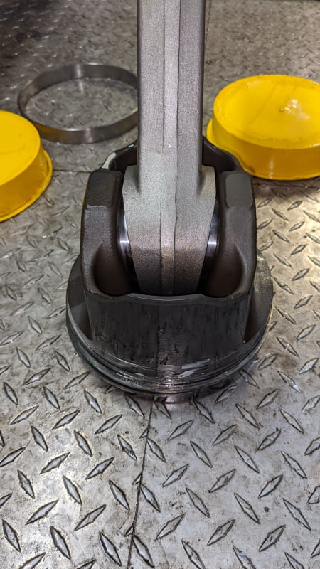
Bonus question: How many have seen a cast steel piston from a Ford 60? Steel pistons are back too.
 
The steel pistons were reintroduced by Mahle under the Monotherm name. Here is one from a Cat:
IMG_20200708_121656_gnzfiq.jpg
 
so now what I need is a non parametric engine design info than ill be able to understand the whole basic picture and yes I agree making a clean sheet engine on a drawing board is a pain BUT they manage to do it in the old days! not perfectly but in reliable
way afterward


by the way using a calculator and paper where do you get all the proportion ( the stress counterbalance and oil film formulas ) to go with it, any source of info still available these days in the era of CAD FEA and CFD ?

Steve
 
TugboatEng - Nice picture illustrating the teepee shaped small end of the connecting rod. The lower half of the pin bearing bore has more area for combustion gas loading compared to the inertia loading on the top half. The piston bosses are moved in at the top for additional bearing area and reduced pin bending. The strength to weight ratio of steel is better than aluminum especially at high temperature.

Steve - In the old pre-computer days we went to the library. Start with Taylor as suggested by GregLocock.

 
I always wondered why the ends of the rods were tapered. I just assumed it was for weight savings.
 
The net effect is a weight savings by allowing a shorter pin with a larger I.D. to carry the loads piston loads. Diesel allowable pin bore pressures have more than doubled in the last 60 - 70 years from perhaps 60 ksi to 140 ksi. Fit, finish and some design tricks account for much of the increase in bearing surface loading but the bending stress limits of steel have remained pretty stagnant. So moving the firing load areas closer together really helps to reduce the bending stress and the amount of steel needed to cope.

Another interesting steel piston was phased into the Series 60 Detroit. There was an evolution from the original aluminum piston skirt through a couple of steel designs.


The 71 series had some interest pistons as well. It was a steel crown with an iron skit but the connecting rod bolted to the wrist pin.
 
All EMD's engine 567, 645, 710 series uses cast steel piston and are floating trunk piston design with only one internal snap ring at the base of the skirt, these 2 cycle diesel engine don't have a intake suction phase like 4 cycles engines does so there's no almost tension on the piston and the rod itself only compression so the snap ring to hold the piston on the trunk free to spin on its own axis

here's a cutaway with temp gradient in this link

 
Status
Not open for further replies.

Part and Inventory Search

Sponsor