Eng-Tips is the largest engineering community on the Internet

Intelligent Work Forums for Engineering Professionals

internal combustion gas or diesel engine clean sheet designing 7

Status
Not open for further replies.

nanokron

Automotive
May 12, 2019
25
0
0
US
ok I finally have a copy from John Manning’s book, Internal Combustion Engine Design, published by Ricardo, 2012. ISBN 978095732920-1

directly from Ricardo engineering :)


here's a few question that I still not fully understand especially concerning the "Cylinder Block and Cylinder head"

especially from the Sketch DRAWINGS to the Final detail BLUEPRINT DRAWINGS before the first procurement prototype engine

1) when designing an engine "cylinder block" DRAWINGS is there any parts of the engine assembly preliminary design DONE before the said cylinder block DRAFTTING Ex: Crankshaft, camshaft, ect .

2) the designing process of the cylinder block DRAWINGS generally does it start with "Bottom Up design" or "Top Down design".

3) in a cylinder block design preliminary DRAWINGS what are the block Features design DRAFTING sequences Ex: A) crankcase, B) cylinders layout, C) lower cylinder deck, D) water jacket, E) upper cylinder deck .

4) How does the interaction Between the different engineers and the draftsman Works? who will be in charge of the designed features?
of the specific engine part for a cylinder block DRAWINGS

5) at last all the above questions BUT for the "Cylinder Head" part

I am interested in the principle behind engine designing DRAWINGS only, not much in CAD or FEA and or CFD. I am just intrigue by the way they design major engine part like in the 50's, 60's and 70's drafting tables and slide rulers! BUT any computer related design subject still appreciated as a feedback :) casting and machining drawings both are in my field of interest

and if any GOOD publication of concern of the above subject and questions I'll be happy to source if I can get them

engine size mostly of my interest would be bellow 1000 CU-IN or about 17 liters in displacement gas or diesel ICE industrial or automotive from 1 to 8 cylinders either inline or v configuration

any reply appreciated

Steve
 
Replies continue below

Recommended for you

Those monotherms aren't cast, they're forgings like most modern steel pistons, hence the cooling gallery having separate stamped/welded cover plates. Like most forgings, they are a nice product for high combustion pressures and extreme durability, but pricey and somewhat limited for new development. Typically they are forged thin for a specific bowl so there isn't much meat left to work with unlike aluminum castings which are cast thick and blank/flat topped, readily accepting of whatever bowl you'd like to machine in.
 
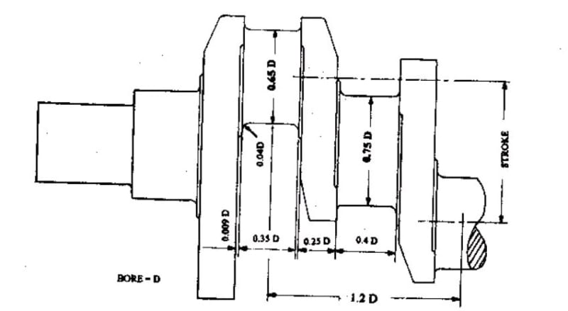
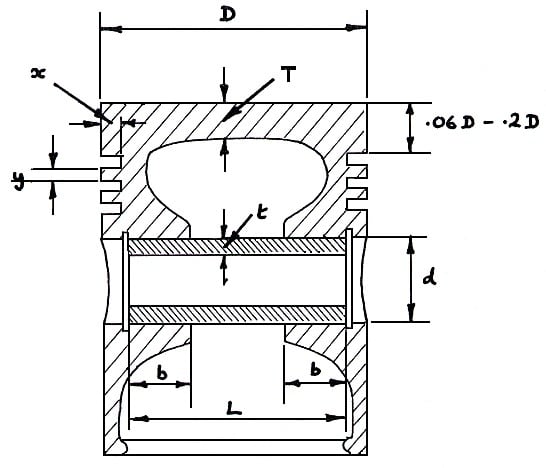
just an update on the subject I started up about 3 weeks ago here's a few examples of what I was looking for

Crankshaft-1_zhklcr.jpg


piston_quhcl6.jpg


are those proportion a form or parameterization

if so what is the terms used so i can search more info on the subject

i am looking for proportions in relation to the bore size ( bore to ratio features sizes ) for the "cylinder block" and "cylinder head" features and dimensions

any publication with those kinds of formula!

i got lucky and found those pics by looking for something else and these came up

P.S. if i am a pain let me know as i don't want this subject to stretch for ever just want to get as much info as i can on this thread

Steve
 
While it will be found that certain of those dimensions may fall within certain relationships to other dimensions, an attempt to design an engine strictly by rule of thumb is sure to end in failure.

Changes to certain engine parameters (e.g. compression ratio, whether the engine has forced-induction or not, rev limit, piston speed and acceleration at redline, etc) will shift those relationships, for example.

You HAVE to crunch the numbers, and even in the old days, they crunched the numbers. They may not have had modern analysis tools available, which meant they had to allow for bigger margins of safety, but they did indeed crunch the numbers the best they knew how to do at the time.

I can tell you for sure that the crankpin journals in the last motorcycle engine that I had apart are not 0.65 times the bore diameter, and the main journals are certainly not 0.35 times the bore diameter in width. And the piston skirts nowadays in such an engine are much, much shorter and do not form a complete circle at the bottom - the unnecessary weight is cut away.

I'm guessing that the sketch you found is for a heavy-duty engine designed for higher cylinder pressure, and much, much lower revs. And perhaps those dimensional relationships are appropriate for an engine with that service. But ... you have to crunch the numbers.
 
This post is probably useless but maybe worth a read.

Over the past 15yrs I have cut up and measured approx 60 engines from 1L budget things from yonks back to new F1 engines.

Heres what I found in terms of lets say the 150-170hp 2L inline four bracket... ranging from about 1985 to 2000.

They all had 4 valves per cylinder.
Some had nice combustion chambers, some had not.
Some had 81mm pistons, others hand 90mm ones...
All had aluminium pistons.
Some had lovely port shapes, others had awful shapes and entry angles.
Some had piston squirters others did not
Some had alloy blocks others had ci blocks.
Some had cast cranks others had forged, one or two had billet items.
Some had 3mm head casting thicknesses others I saw walls 6-8mm thick.
Some had a head coolant volume 3 times of many of the others.
Most had same waterpump L/per/Min rate.
All had same thermostat opening temp.
Some had carbs, others Kjet, rest EFI.
Some had ci rings, others steel, others uber bimetal types.
Some had ladder style sump girdles, others 2 bolt conventional main caps, others 4 bolt.
Some had long rods, others short, some with drillings to small end others not.

None of the above ''good bits'' were seen on any one engine, but each was a mix and match of all/some of the above.

All engines made about 160hp... with similar curves.

I cant answer all of your points above in op but in terms of engine design, a lot of it is ''follow what works''.

I have more experience in F1 and I will say that the Formula to follow comes first, then where the engine block has to fit in terms of space and aero, then the rest gets designed.

The only big decision I would be making in the morning if I was to design an engine with 2 cams and 16valves would be if I wanted to be able to get at the head bolts with cams in place, or...go for a more favorable valve separation angle which may see the cams sit over the head bolts and require a 2 piece head or the head bolt counterbores eating into the lower cam journals which is no harm either within reason.

Brian,


what I was meaning is you start with proportions based on feature to bore size ratio, if it is done on cad you float the model with these baselines numbers for each features proportions EX:( like a 3d model of a piston base on a preliminary sketch ) and THEN you crunch the numbers and lock the constraint one features at a time

from what I read in the book

Parametric Design of
Diesel Engine Inlet Ports

is that there's rules you have to follow in some orders

like example the cylinder head bolt pattern is define by the 3D model of the cylinder head and not NECESSARILY by the engine block because the constraint of port design will dictate the bolt holes locations ( aside of other related cylinder head features ) the bolt size and the bolt length ( with the proper stress, total load clamping and port, cooling flow analysis )

my assumption was that the cylinder block head bolt location WAS ALWAYS DEFINE FIRST by the cylinder block so I was WRONG assuming this

the above book title really explain that process really well!

Steve
 
Chrysler found a work around for this on the Gen 2 hemi, that is still practiced today on top fuel engines, if I'm not mistaken [wink]

"Schiefgehen wird, was schiefgehen kann" - das Murphygesetz
 
Engine design starts with what is its application is going to be. What machine or vehicle will it be powering? Next would be what power it is supposed to produce for the application. All that should help the design team or designer determine what the size of said engine will be. Remember an engine for a granny car to run to the store will be way different than one used for a locomotive, container ship, or a KC-97 airplane.
Once you have the application and HP power requirements, and any weight restrictions for the application, then the engine design can start. In the old days and I would think now as well all the chosen design of major components of the engine, if for a multi cylinder engine, is all first tested as a single cylinder engine. That means at that particular point none of the parts are the correct size of what the final engine design will be.
This is where all the components are checked and tested and tweaked so the final parts to be used will be some what proved for the particular design. The internal rotating parts and the case that will contain them, will all be an integrated design process, your not going to design say the crankshaft first and ignore how it will be fitted and held in the containment vessel, and in say the old large piston aircraft engine days
the most important thing to design would be the cylinder locations for the best cooling effect then the rotating member (crankshaft) would be designed to accommodate that particular crankcase design.
So unlike some say that the first items to design are the rotating internals, that would not be true in the particular large aircraft engine I'm writing about. The crankcase and cylinders arrangement would be first
then everything else made to fit.
 
somehow the crankshaft will define the displacement of a specific engine because of its stroke , but if you can't have an accurate LOCUS or BANGO interference fit how you will be able to assess the crankcase volume if you don't have the crankshaft modelled
FIRST because the crankshaft dynamics will have to be sorted out before the crankcase is modelled ( bending analysis, torsional, stresses ,oil film loading and balancing) now I understand why the crankshaft needs to be modelled first because it will define the stroke of the engine with its dynamics model

it is technically the same principle for designing a transmission if you know the torque rating, the rpm range the layout
first you need a gear analysis of all your internal component BEFORE making the transmission case because if you do it the other way you will never know how big and wide the gears need to fit that case the same goes for designing an engine!

by the way I found quite a few articles on crankshaft modeling online and all I can say it is really a fascinating subject to read :)
 
Status
Not open for further replies.
Back
Top