CTengIS
Mechanical
- Jul 25, 2023
- 42
Hi all.
I have what may be considered a metrology/inspection related question but since it's strongly GD&T related too I think that may be here is the best place to ask.
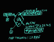
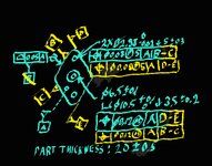
Consider interpretation per ASME Y14.5-2018. A part has a periphery that is some polygon. The bottom flat surface is used as the primary datum feature A, and the polygon shaped periphery (which is nominally normal to the bottom), as an Irregular Feature of Size that gets an all-around profile of a surface tolerance relative to datum A, is used as the secondary datum feature B. Some other features and Features of Size on the part get profile and positional tolerances relative to datums A primary (taking away 3 degrees of freedom), B secondary (taking away another 3 degrees of freedom).
I realize that in many cases it would be appropriate and handy to reference B at MMB, which would allow to make a fixed size polygonal pocket as Datum Feature Simulator for B as part of an inspection fixture, but let's assume that Datum Shift is not wanted in this case, a fixture is not used, and datum feature B is referenced RMB.
And here is the question:
With CMM inspection without physical Datum Feature Simulators, how difficult would it be to obtain a datum (axis and plane) by simulating the Related Actual Mating Envelope of the polygonal peripheral shape and using it as the non-physical Datum Feature Simulator (or the calculated True Geometric Counterpart) for datum feature B? I mean, once the datum features are sufficiently probed by the CMM, would an average Inspector using the average inspection software be able to establish the Datum Reference Frame (or the measurement coordinate system) easily, including the step of having the RMB TGC for datum B simulated, as a basic and routine practice, or would it be considered an advanced, laborious and difficult task?
Last edited:


