Continue to Site

Eng-Tips is the largest engineering community on the Internet

Intelligent Work Forums for Engineering Professionals

  • Congratulations KootK on being selected by the Eng-Tips community for having the most helpful posts in the forums last week. Way to Go!

Irregular Feature Of Size as Datum Feature on CMM

CTengIS

Mechanical
Jul 25, 2023
42
Hi all.
I have what may be considered a metrology/inspection related question but since it's strongly GD&T related too I think that may be here is the best place to ask.

Consider interpretation per ASME Y14.5-2018. A part has a periphery that is some polygon. The bottom flat surface is used as the primary datum feature A, and the polygon shaped periphery (which is nominally normal to the bottom), as an Irregular Feature of Size that gets an all-around profile of a surface tolerance relative to datum A, is used as the secondary datum feature B. Some other features and Features of Size on the part get profile and positional tolerances relative to datums A primary (taking away 3 degrees of freedom), B secondary (taking away another 3 degrees of freedom).
I realize that in many cases it would be appropriate and handy to reference B at MMB, which would allow to make a fixed size polygonal pocket as Datum Feature Simulator for B as part of an inspection fixture, but let's assume that Datum Shift is not wanted in this case, a fixture is not used, and datum feature B is referenced RMB.

And here is the question:
With CMM inspection without physical Datum Feature Simulators, how difficult would it be to obtain a datum (axis and plane) by simulating the Related Actual Mating Envelope of the polygonal peripheral shape and using it as the non-physical Datum Feature Simulator (or the calculated True Geometric Counterpart) for datum feature B? I mean, once the datum features are sufficiently probed by the CMM, would an average Inspector using the average inspection software be able to establish the Datum Reference Frame (or the measurement coordinate system) easily, including the step of having the RMB TGC for datum B simulated, as a basic and routine practice, or would it be considered an advanced, laborious and difficult task?
 
Last edited:
Replies continue below

Recommended for you

Since your question is related with the CMM inspection, I would say to post it here

or other CMM forums for a more pertinent answers
 
Hi, CTengIS:

Well, it depends on polygon shaped periphery. Your CMM programmer needs to identify features and make sure there is functions with its software to do best fit.

Best regards,

Alex
 
Hi greenimi,
Thanks, I'll check the forum you suggested and other CMM resources. But if it's OK, I'd also like to get some input from the GD&T experts here. I got an impression that many here are with strong ASME Y14.5 background and can understand the theoretical side of my question thoroughly, and are also experienced enough at applying it on a high level in practice to know what to expect from inspection.

Hi jassco,
Thank you! Are you saying that if it's a common polygon such as a triangle, square, hexagon, rhombus, parallelogram etc. the software could have an available function for it, but if it's some more irregular or uncommon shape it may become a problem to generate a suitable Related Actual Mating Envelope as the Datum Feature Simulator to obtain a secondary datum from?
 
Hi, CTengIS:

Hexagon PC-DMIS is one of top CMM programs. I did not use it myself. But my former colleague used it all the time and I used to watch how he programmed. A common polygon is very easy to align using either least squared error or Max./Min. best fits. Below is a quote from ChatGPT on Hexagon PC-DMIS.

"Yes, Hexagon CMM software can perform best-fit alignments for polygon geometries. Their PC-DMIS software, for example, has best-fit alignment features that allow you to align complex shapes, including polygons, based on specified tolerance zones. You can select specific reference points or use all measured points on a polygonal shape to find the best-fit solution based on the least-squares method or other fitting algorithms.

This capability is particularly useful for aligning parts with non-standard geometries to a coordinate system or aligning them for GD&T evaluation."

PC-DMIS is very powerful. If you are familiar with API, you can basically do anything you want.

Best regards,

Alex
 
Hi, jassco,
Thank you for this info. It is helpful.
A follow up question: let's say the part's "all-around" periphery is some more complex and irregular shape that also includes some curves, and not a shape that has default best-fit alignment options in the software. According to your experience or impression, is a typical current CMM software likely to allow the programmer to simply select all the surfaces that form the closed shape from the imported CAD model and define that entire shape as a datum feature (3 degrees of freedom secondary datum feature, or 5 degrees of freedom primary datum feature).
 
As far as I can tell from the documentation on the Hexagon PC-DMIS site, there is no specific option for regular polygons or any other polygons. There is some reference to using complex surfaces and a profile tolerance for them and then applying a fitting operation and manually tying explicitly defined datum stand-ins to the complex surfaces. It does not appear to offer maximum/least material boundary fitting for enclosing features.

Chat-GPT is designed to produce answers people think are reasonable, but Chat-GPT frequently lies to make things pleasing; the Chat-GPT makers call it "hallucinations." There's a lawyer who may have been disbarred for using Chat-GPT to write a brief, just a little one on an uncontroversial topic. Only one problem. Many of the cases cited as support don't exist.

The underlying problem is that Chat-GPT does not understand the underlying meaning and is looking at patterns of words. If one asks it something novel, a topic it wasn't specifically trained on, it will do like a 5th grader who didn't read the assigned book but now has to give an oral book report in front of the class. It's always taking a best guess rather than certainly knows.

Some have the function to report where it collected the information, so we'll see if that makes a difference.
 
Hi, CTengIS:

Yes, of course. There is no part that you can't measure as long as features on the part are accessible. I can even do it myself on CAD environment with a custom function (API). You import point clouds into your software and you can align them with the function or manually. You can even do it using Matlab. Zeiss machine is also very capable.

Hi, 3DDave:

Regard Chat-GPT or Bard, you will need to believe something, otherwise you would have to raise a cow to produce milk. I create a lot of program codes using Bard, I am yet to see "hallucinations".

Best regards,

Alex


Sorry jassco/Alex,

I expected you to provide proof that Chat-GPT was correct about Hexagon PC-DMIS rather than changing the subject. What it generated is apparently a hallucination, so now you have seen one.
 
There is some reference to using complex surfaces and a profile tolerance for them and then applying a fitting operation and manually tying explicitly defined datum stand-ins to the complex surfaces.
Hi 3DDave,
That seems interesting. I visited the PC-DMIS website but I'm not sure where to look for that type of information. Could you maybe provide a link to that specific info, about fitting to a closed shape and then using datum "stand-ins" as part of establishing a datum reference frame for measurement? Although I am not a CMM user myself I'd like to have general understanding of that process.
 
I wish - I am not a PC-DMIS user. I can see the elements they make available to build the inspection programs and the postings on other forums about how they are used. If you need more I suggest contacting them for a demonstration to show how they would do this; perhaps by a visit to their headquarters.
 
Hi, CTengIS:

Can you post an image to show what you want to achieve? I have a feeling that you are trying to do something that may not be reasonable. Are you familiar with datum selection criteria? I went to a training some 10 years ago with Mark Foster. If I remember correctly, there are four criteria for selection of datum features.

On CMM machines, you generally rough-position your part on a fixture. Then PC-DMIS will probe and align the features you selected to its coordinate system. The 3:2:1 alignment is most popular one.

Best regards,

Alex
 
Hi jassco,
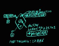
I made a simplified example quick hand sketch on my phone. Sorry for the way it looks but I hope it's readable.

1000012796.jpg

This rhombic part is an aluminium connector that locates two 3 mm dia. dowel pins near the acute angle corners. It mounts on the far-side flat face that was selected as datum feature A, and on two surfaces of the periphery: either the two left side surfaces forming an obtuse angle or the two right sides surfaces forimg the other obtuse angle. Because the part is symmetrical it can be used both ways. The counterbored clearance hole in the center is for a cylindrical head screw for clamping down the part against datum feature A when the other 2 surfaces that locate this part are already in contact with the mating part.

I could make each mounting option's pair of lateral mating surfaces separate datum features such as for example B-C (left side) and D-E (right side), and reference the holes to A,B-C and then again to A,D-E. That would represent the mating conditions most exactly and would imply simpler datum simulators, but on the other hand it would double the amount of requirements for the holes and require two inspection set ups for checking the holes (and other features I didn't show in the sketch). When I attended GD&T training some years ago, I was taught that if there are two possible interfaces due to symmetry, it's better to unify them so that the two interface features or sets of features become one datum feature, as long as the interrelationship between those features is controlled tightly enough (a different example of same principle would be, if a rectangular part is mounted on either 'side A' or 'side B', the width between those sides could be used as a datum feature of size, and used in one datum reference frame instead of having two different datum reference frames).

"four criteria for selection of datum features" sounds interesting and useful - do you recall what they are?
 
Last edited:
Does the mating part uniformly contract around the periphery of the part currently used as datum feature B?

That is the implication of the current datum feature symbols and references .
 
Hi, CTengIS:

We don't know how this part works in its assembly environment. Datum feature B is questionable unless it is truly nested in a pocket of the same shape.

Regarding the 4 criteria, James D. Meadows summarized them the best using these 4 words below in his book ("Geometric Dimensioning and Tolerancing"):

1. Functional;
2. Representative;
3. Accessible;
4. Repeatable.

In James' book, there is a figure (Fig. 11-19 on page 240) that is almost same as yours. He is an ASME Certified Sr. Level GDTP. He used to be a vice-chairman on Y14 committee if I remember correctly.

G. R. Congorno summarized these 4 criteria as follows in his book ("Geometric Dimensioning and Tolerancing for Mechanical Design").

Datum Feature Selection:

Datum features are selected to meet design requirements. When selecting datum features, the designer should consider the following characteristics:

1. Functional surfaces;
2. Mating surfaces;
3. Readily accessible surfaces;
4. Surfaces of sufficient size to allow repeatable measurements.

These are the exact words from his book.

Best regards,

Alex


G. R. Cogorno - just one "n" in the last name.

If the desire is to predict how a part performs in an assembly then the features that locate and orient the part in that assembly are the best predictors of that performance when used as datum features. It is a shame that so few of the examples in the standard make use of such selections.

Likewise any material condition modifiers should match the mating features. If the mate is an interference fit, then RMB (R) and if a clearance fit then MMB (M).
 
Hi jassco and 3DDave,
The assembly is like I described in the paragraph right beneath the image in my previous post. So it's not the entire periphery being in contact with the mating part but half of it, with the caveat that we never know which half because of the intentional symmetry and the fact it can be mounted either way. To be exact, it's not really half the periphery either, as the rounds in the corners are not in contact. There are fillets with smaller radii on the mating part to create a gap in the corner and allow just the flat portions to be in contact.

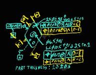
Perhaps the option to reference the holes to A,B-C and then again to A,D-E (when the B,C,D,E datum features are the flat portions of the rhombus), as in the below modified image is more functionally representative, but the reasoning to make a single datum reference from the entire periphery is: if the entire periphery is produced and measured accurate enough as a whole without a significant added cost, then the results of using it as a single secondary datum feature (as in the previous version) should be similar enough to breaking it down to two seperate datum reference frames, but with the advantage of not requiring two different inspection set ups or alignments. But that "shortcut" would only make sense if deriving a datum from an Irregular Feture Of Size at RMB doesn't make it more complicated, hence the question.

1000012899.jpg
 
Last edited:
Hi, CTengIS:

Can you show an image of your assembly? What go through those two small holes, dia. 2.88+/-0.02? I doubt that half of the periphery is positioned. Otherwise, why do those two small holes have such a tight tolerance (+/-0.02).

Best regards,

Alex
 
Hi jassco,
The part is clamped against datum feature A and makes contact at either datum features D-E (with equal precedence) or B-C (also with equal precedence), because the design is symmetric. The 2 accurate holes are for pres-fitting the dowel pins that this part locates in the larger assembly (that's also the reason for the projected tolerance zone).
 
This may not really answer your question, but the all-around profiled periphery you are referencing as datum feature B in the first version qualifies as a "linear extruded shape" from section 7.3(f) and the chart in figure 7-3 of ASME Y14.5-2018, providing a datum of an axis and a plane. It's referenced secondary in your case, therefore it constrains 3 degrees of freedom as you mentioned, out of the 5 DOF potential of its geometry as shown in the chart.

Should a decent CMM software support establishing that datum and applying the constraints relevant to the position controls easily? I'd say it should, I would say a decent software should support all the datum types (or as they are sometimes referred to, "invariance classes") of chart 7-3. But whether they actually do is a question someone with CMM experience is more qualified to answer.
It does seem that unfortunately, at least one major player in the metrology software field gets away with not supporting this datum type:

"This invariance class is not supported from the GOM software"

So it may be specific to the software your inspectors will use. But I hope someone can give you a better answer based on experience.
 

Part and Inventory Search

Sponsor