Eng-Tips is the largest engineering community on the Internet

Intelligent Work Forums for Engineering Professionals

Is a MMB callout on the datum of a feature control frame for perpendicularity of a plane illegal?

Status
Not open for further replies.

Ev-36XPro

Mechanical
Oct 9, 2018
6
0
0
US
(Per ASME Y14.5-2009)

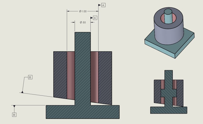
I just ran into an old drawing which has what I have now learned is datum shift. This concept is quite new to me, but I have become the person to settle an argument of if the usage of it in a drawing is illegal or not (simple example below). The first picture is the drawing as is. One person is saying the use of MMB on Datum A for the perpendicularity requirement is illegal because you cannot have datum shift on a surface. I see where he is coming from because it does not make sense for a functional gauge (although this part is only inspected with a CMM). However our inspection team raised the point shown in the second drawing, which is would it be correct if you added the FCF to Datum A, referenced off of B. And would that result in the same part? So are both illegal, one, or neither?

Also is MMB used on the datum legally for the dowel pin? I believe so because both are axis and it makes the most sense for a functional gauge.

option_1_mwbzjv.jpg

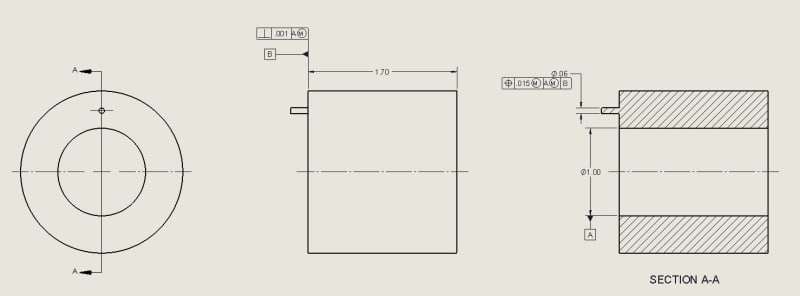
What the drawing actually is.

option_2_xh9ayp.jpg

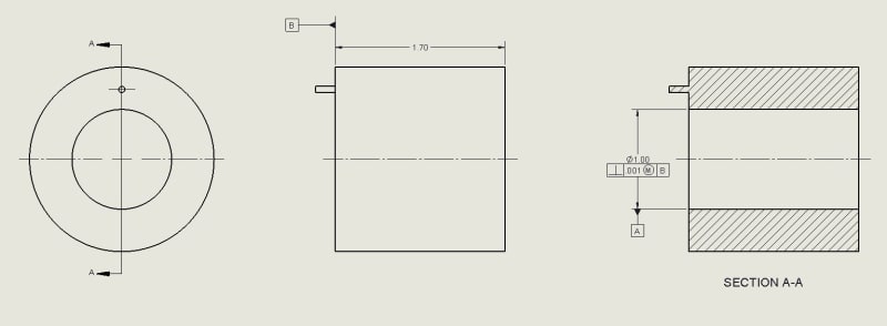
Inspection team's suggestion.

example_nmcibw.jpg

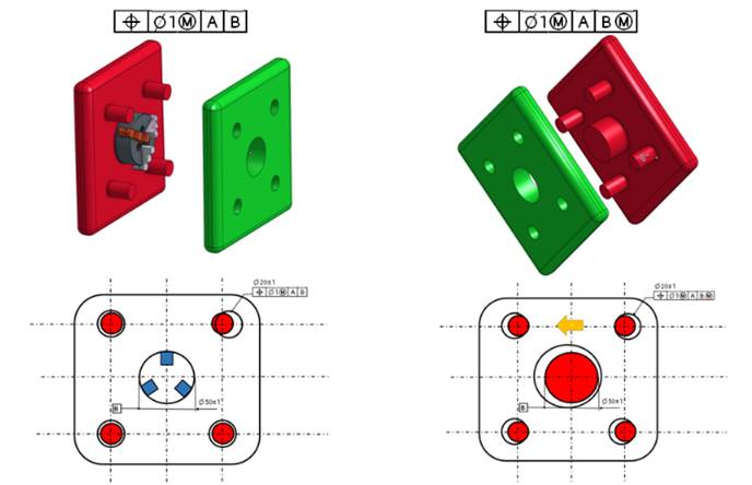
I also included this because it helped me better understand datum shift.


Thanks everyone! [glasses]
 
Replies continue below

Recommended for you

First question: ASME or ISO?
If ASME which version?

Now let me take a stab on it:
perpendicularity of the cylindrical surface to B primary looks legit to me. A
Perpendicularity of the planar surface to A(M) looks also okay.

You just have to decided for the function of the product which is primary and which is secondary.
Don't let the tail wag the dog, meaning the inspection to drive the product definition.

Decide what you need for the function and then make the gage from there.

A(M) is the datum shift. B(M) is illegal.

On the first drawing B secondary in the position callout does not bring any value. Might be there for simultaneous requirement, but as a stand alone callout B does nothing.


Thanks for the reply greenimi. It is indeed ASME, specfically ASME Y14.5-2009.

To give some background on the design intent, this is a stator which mates with a rotor. The most critical dimension is having sufficient clearance or "air gap" between the rotor and stator. The rotor is attached to a gearbox which Surface B mates to. If B is not perfectly perpendicular to A, then we lose clearance. However, if the internal diameter of A is near the higher tolerance range, then the design can tolerance B being less perpendicular to A.

For the first drawing, is the FCF on surface B executing this design intent and providing "bonus tolerance"? (I know it's actually datum shift [bowleft] but just for design purposes it makes more sense to me to think of it as bonus tolerance [hammer] Ahhhh! Alright, it's datum shift!)
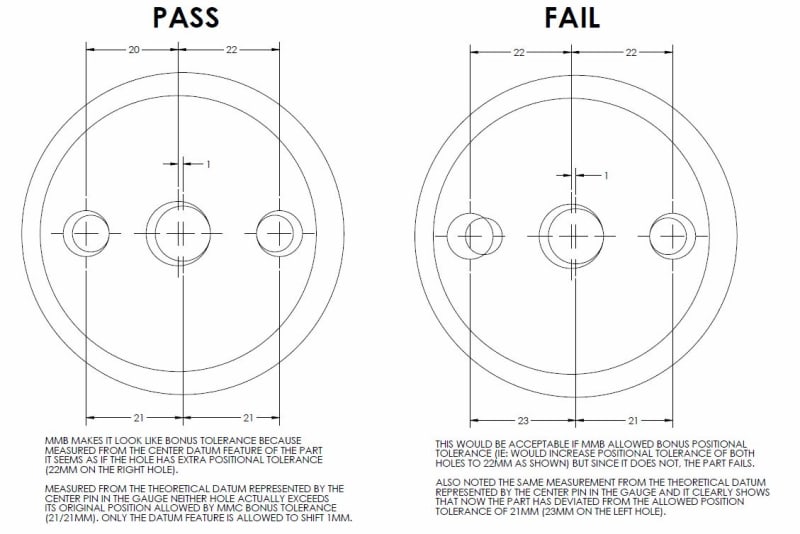
Thanks again for your help.
 
Ev-36XPro said:
For the first drawing, is the FCF on surface B executing this design intent and providing "bonus tolerance"?
Your FCF is certainly allowing datum shift of your primary datum A. In your case (and others) it will deceptively "look" like bonus tolerance, but as you clearly know datum shift is NEVER actually considered a bonus tolerance.

See the discussion in the thread ( I always link to this when the question comes up because its what helped really solidify my understanding of what datum shift is and isn't and hopefully its helpful to others. I have also attached the graphic that CH developed (all credit goes to him for it - from the same discussion, post on 17 May 18 14:59) that was really instrumental in my understanding as well.

From that discussion arose what I found a useful way to think about it - what datum shift does is actually loosen the relationship between the datum feature and its datum feature simulator. The relationship of the allowable tolerance zones of the other controlled features on the part back to the datum feature simulator does not change. I also developed the below graphic to illustrate this point, and further show why in CH's second example with two holes on either side of the central datum feature it does not act like a bonus tolerance (I utilized the same basic dimensions as the original example).

EXAMPLES_-_gauge_assembly_pass_fail_hayyex.jpg
 
Chez311, thank you for the information and link. It was helpful to read your thought process in the other thread. I am now trying to visualize a functional gauge, and am wondering if this is correct. This is based on my understanding of "what datum shift does is actually loosen the relationship between the datum feature and its datum feature simulator". So the large image is of a functional gauge which allows datum shift because a bigger stator ID means the gauge can pass through, even if B is less perpendicular. But, if the drawing does not have the MMB on Datum A in the FCF, then the gauge would look like the smaller example, where it would be sized to the exact ID of the stator (although the functional gauge doesn't really "function" at this point because then there is no longer a way to inspect for perpendicularity. You'd probably have to adjust the sizing element to a specific amount slightly less than the ID, which would be dependent on the height of the stator).

My other question (based on the example by CH), is if I want to inspect a part like this example on a CMM, could I calculate the tolerance limits as an equation dependent on the ID of A? Sort of like a bonus tolerance?

Thanks! [tiphat]

functional_gauge_zyparj.jpg
 
Ev,
For the case of A at MMB, As the actual bore is produced larger in size you will have more amount of available play during fitting datum feature A over a gage shaft. This play may assist you to force an orientation of the part so that the entire datum feature B face can be fitted into an exactly .001 wide tolerance zone perfectly perpendicular to the gage shaft. This allows a face B produced with larger perpendicularity error to pass the inspection. Note that even though this concept allows you to accept features with larger error, this really isn't a bonus tolerance. Bonus tolerance is related to MMC/LMC and what it does is allowing the tolerance zone to enlarge under certain circumstances. In your case the tolerance does not enlarge - it is fixed at .001 exactly - but the additional play at the interface between datum feature A and its' simulator allowed by MMB allows you to fit a less perpendicular feature B within that same tolerance zone. Now it is up to you to decide if this is scheme is adequate for your part functionally or not.
 
greenimi said:
On the first drawing B secondary in the position callout does not bring any value. Might be there for simultaneous requirement, but as a stand alone callout B does nothing.

greenimi, take a look at ASME Y14.5-2009 fig. 4-21 illustration (c). Are you sure that B secondary "does nothing"?
 
3DDave and Belanger said:
3DDave (Aerospace)14 Dec 18 15:17
I think 4-21 (c) is a possible outcome, but not the only outcome of the allowable variations for that datum reference frame. Without knowing the length of datum feature A and width of the face it isn't possible to know that datum feature B will make full face contact when A is at LMC. Based on the proportion in the diagram, with the perpendicularity tolerance that is twice the diameter tolerance, the LMC surface would be binding against the MMB datum simulator at the same time there is face contact. This ignores that at LMC the feature could be bent enough to not allow rotation anyway and the face would also make no contact.

For me, the apparent problem with 'datum precedence' is that, aside from interference fits and planar contacts (I feel like I'm missing a case), there is nothing in real mechanisms that preclude shifting parts to accommodate clearances.

If, for no good reason, one datum feature has a large amount of clearance and one later in the chain has very little, the later one may be the one providing the greater control. But, when it comes time to install the part, the installer cannot tell the difference, so is there necessarily significance to the order they appeared on the drawing?

What was not in 4-21 was the bold move of suggesting |B|A(M)] and showing how to evaluate the MMB when A is secondary.

Belanger (Automotive)14 Dec 18 17:04
3DDave -- I've always felt the same about Figs. 4-21(c) and (d). If the pin is made at a smaller size, then datum feature B sort of takes over as the main balancing feature. We don't know the length of the pin etc., so it's kind of a strange scenario.
Should I presume that your last comment was tongue-in-cheek? Because having B as the primary datum would make a lot more sense from a practical point of view -- and that's what they had shown in both the 1994 and 1982 standards. Maybe boldness is what they were after in 2009


Well, maybe you are correct but I guide myself after what has been discussed here in this thread and from which I have posted some relevant quotes. The discussion is "Virtual Condition Check at RFS"

Edit: added discussed thread link
 
greenimi, thank you for the reference.
I don't want to hijack this thread but I am tempted to ask - what part of those quotes made you conclude that a secondary planar datum feature theoretically perpendicular to a primary datum feature of size specified MMB does not influence the outcome of fixturing the part for inspection? Or did I misunderstand your statement?
 
Sem,

I'm interested myself for more pertinent opinions about this issue. So far, I think the concept (value added of secondary datum in the FCF in the shown case and also in the fig 4-21 case) is debatable. I would ask more people -experts- for their general opinion. For me, happens to belive that is no value added.

See this quote from 3Dave

3Dave said:
Figure 4-21 (b) and (c) demonstrate that the secondary reference is not required in that example. A DOF analysis shows that the plane in [A(M)|B] doesn't control any independent DOF(s) for the 4 holes. Particularly (b) shows a lower priority datum reference gaining orientation control over higher priority reference in an ad hoc fashion. I see it as an example that should be clearly labeled "Not Recommended" along with an explanation.

Compare '2009 4-20 and 4-21 to '1994 Figure 4-18.


Is he correct? Not sure...but it is a relevant opinion and again, it happens for me to think he is right. I know other people think otherwise.
So the whole concept is questionable....
 
Recommended or not, it doesn't take an "expert" to tell that |A(M)|B| might reject some parts that would be acceptable for |A(M)|. The rest is a matter of what suits the function best. Without delving into details I would probably just through a guess that |B(M)|A| might be a better choice. Again - that's only a guess. Regadless - B secondary definitely does something that is not there with just |A(M)|.
 
It sure is. I meant |B|A(M)|.
Thank you for the correction.

In case Ev-36Xpro will want to know:
There is a difference between |A(M)| and |A(M)|B| in the feature control frame for the pin. For |A(M)| the full gap between the produced bore A and the gage shaft can be utilized for play (rotating the part until further rotation is constrained by the contact between the bore and the gage shaft). In the case of |A(M)|B| - B as a secondary planar datum feature will need to contact its' datum feature simulator at two contact points, and might limit some of the play in orientation that is available in the first case. Therefore there is more available mobility in the gauging process for the case of |A(M)| - and the consequence of that is that this mobility can be utilized to find an orientation of the part in the fixture that will allow fitting the pin within a gage hole representing its' maximum material virtual condition, and accept the part, which might have been rejected in case of |A(M)|B|.

Side note - according to the rules in Y14.5 regarding degrees of freedom constraints, datum feature and datum feature simulator A should constrain (edit: alone) the same rotational degrees of freedom that B secondary may influence in the scenario described above. In practice, the process would conform to those rules only if A was specified RMB. With A specified MMB, the physical behavior during gaging would be different, as the secondary datum feature might override datum precedence by constraining degrees of freedom that A constrains only partially. Nevertheless, since this scheme is shown in a figure in the standard, it is legitimate (edit: although probably should mostly be avoided).
 
After re-reading the described design intent in Ev-36Xpro post from 26 Apr 19 14:52, I suggest considering:

* B as the primary datum feature.

* Qualifying datum feature A with position perpendicularity MMC referencing B - as suggested in the second drawing in the OP.

* Controlling the dowel pin for position MMC referencing B primary and A at MMB secondary.

Edit: Another suggestion - not along the lines of the OP but perhaps even more appropriate functionally: since the bore designated as datum feature A is not supposed to mate by contact with the stator but should maintain clearance with it, It shouldn't be datum feature. If there is a pattern of dowel pins that connects datum feature B to the corresponding face of the gearbox, this pattern should be the secondary datum feature, datum feature B the primary - and the bore controlled for position referencing those datum features.
 
Sem_D220 said:
For the case of A at MMB, As the actual bore is produced larger in size you will have more amount of available play during fitting datum feature A over a gage shaft. This play may assist you to force an orientation of the part so that the entire datum feature B face can be fitted into an exactly .001 wide tolerance zone perfectly perpendicular to the gage shaft. This allows a face B produced with larger perpendicularity error to pass the inspection. Note that even though this concept allows you to accept features with larger error, this really isn't a bonus tolerance. Bonus tolerance is related to MMC/LMC and what it does is allowing the tolerance zone to enlarge under certain circumstances. In your case the tolerance does not enlarge - it is fixed at .001 exactly - but the additional play at the interface between datum feature A and its' simulator allowed by MMB allows you to fit a less perpendicular feature B within that same tolerance zone. Now it is up to you to decide if this is scheme is adequate for your part functionally or not.

For this comment, I think I'm following and understand how the datum shift impacts the inspected parts. But could some comment if the exact same range of parts would pass inspection of the callout was flipped per my original post? So the FCF would be moved to Datum A and say: |perpendicularity| .001 (M)|B|

This type of FCF clearly gives bonus tolerance, but if someone asked me to build a functional gauge I believe they would look identical. Any thoughts on this would be greatly appreciated and a big thanks to everyone's valuable input so far!

[thanks2]
 
Status
Not open for further replies.
Back
Top