Continue to Site

Eng-Tips is the largest engineering community on the Internet

Intelligent Work Forums for Engineering Professionals

  • Congratulations SDETERS on being selected by the Eng-Tips community for having the most helpful posts in the forums last week. Way to Go!

Is it valid to have a Free-State symbol here? 1

Status
Not open for further replies.

SeasonLee

Mechanical
Sep 15, 2008
917
Please ref to the figure below, two questions need help:

1. Is it valid to have a Free-State symbol within the flatness FCF? Since the restraint note on the drawing will override the Free-State default condition, so I will say No, am I right?
2. What's the meaning of the 2nd segment flatness callout?
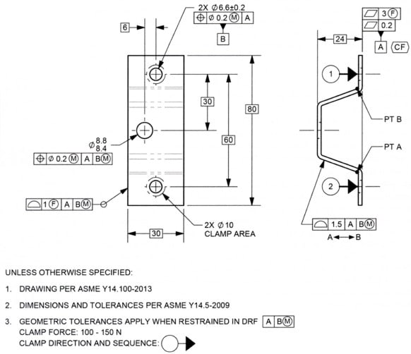
2020-06-22_114334_cd3hw0.jpg


Thank you for the help

Season
 
Replies continue below

Recommended for you

Season,

I mean the end result is the same in both cases:

CF planar feature controlled within 3mm flatness in the free state
CF planar feature controlled within 0.2mm flatness in the restrained state

Only the method of achieving this is different:

(22 Jun 20 19:05)
General restraint note applied - UOS all tolerances apply in the restrained state
3mm flatness otherwise specified with a (F) free state symbol

(22 Jun 20 20:59)
UOS all tolerances apply in the free state
0.2mm flatness otherwise specified with a restraint note
 
Thank you, chez311.

For the second post figure, for what I understant from you: the top segment flatness 3 is still under Free-State condition, would you please advise for what reasons?

Thanks

Season
 
chez311

I understood now, Thank you.

But need more detailed interpretation on :
chez311 said:
Say the 1.5 profile tolerance, in your (22 Jun 20 19:05) figure it would apply in the restrained condition since we would assume the note applies UOS. In your (22 Jun 20 20:59) figure it would apply in the free state.

Season
 
For the second post figure, for what I understant from you: the top segment flatness 3 is still under Free-State condition, would you please advise for what reasons?

Only the designer would know truly why they wanted such a specification. One reason I could surmise is that in the free state one might want to limit variation between the two flat faces because even though the assembly/restraint forces might pull them into contact/flush with the mating surface it might be desirable to limit the amount the bracket has to bend to do so (1) to limit distortion of other features and (2) to limit stresses induced in the bracket due to such deformation during assembly.

As to your second question, I'm not sure what further clarification you are looking for, but I'll do my best.

(22 Jun 20 19:05) this drawing has a general restraint note that applies to all tolerances as the default condition UOS. The 1.5 profile tolerance is NOT otherwise specified with an (F) free state symbol or other overriding note, therefore it must be measured in the restrained state per the general restraint note.

(22 Jun 20 20:59) this drawing has a restraint note that only applies to features with the (3) flag, the default condition in this case would be that the tolerances apply in the free state UOS with this flag. The 1.5 profile tolerance does NOT have said flag, therefore it must be measured in the free state.
 
Season,

Are those two examples ((22 Jun 20 19:05) and (22 Jun 20 20:59)..you provided from some training materials or from an actual drawing?
 
Thanks for your detailed interpretation, chez311
Those examples are not from actual drawing.

Season
 
Greenimi,

Greenimi said:
Dean,

The words in 3.3.23/ 2009 are related with the symbology only and not the continuous feature CF definition (and I would add applicability).
At least this is the way I, personally, read the way the standard is written and structured (chapters, paragraphs and "verses")


3.3.23 Continuous Feature Symbol This symbol indicates a group of two or more interrupted features as a single feature. See Figs. 2-8 through 2-10 and 3-11 and para. 2.7.5.

In the 20 or so times I've shown the options, then asked engineers whether they preferred to control coplanarity with profile, or instead with flatness using <CF>, every one of them have preferred flatness using <CF>.

The words in the standard support this approach, and with unanimous support from those I support, why try to unjustify its use? Just as 3.3.2 provides instructions for how to use and apply datum feature symbols, 3.3.23 provides how to use and apply the continuous feature symbol. What advantage is gained by choosing not to use a helpful and intuitive method that has clear words supporting it in the standard? I will give you that there are no examples showing the practice of using <CF> with flatness or, for instance, perpendicularity, but I think you and I agree that the words are the "law", and the figures are only to clarify.

Dean
 
Dean_Watts said:
...and intuitive method that has clear words supporting it in the standard

I will give you "intuitive".
About "clear words" I have to think about. Still not convinced, but I do not want to turn this thread into a philosophical one.

Lets agree to disagree on this one.

P.S. I cannot believe I am still disagreeing, but that's who I am. I am not really giving up easy.

 
Dean said:
The words in the standard support this approach, and with unanimous support from those I support, why try to unjustify its use?

Because by the time it was added to the standard, there was already a well established and even better-supported (to this day) way to achieve coplanarity and that is using profile of a surface. The standard and the field of knowledge it defines are wide and confusing enough without multiple ways to do the same thing that all users are forced to learn in order to be able to communicate with each other through drawings.

Would you like some new additional traffic signs with equivalent meanings to existing ones added on the roads for diversity? That would be a bad idea, regardless of how intuitive the new signs are designed to be. The damage from drawing misinterpretation may (in the majority of cases) be less potentially catastrophic than not understanding a traffic sign on the road, but it shouldn't be taken lightly either.

There was no way to treat an interrupted feature of size as a single feature for rule #1 verification before CF was added, so it should only be reserved for that.

Just as you suggested recently on another thread that 5 closely related boundary terms used in Y14.5 should be deleted and replaced by wider use of "maximum material boundary" and "least material boundary", I also think it is better to minimize interchangeable tolerancing methods such as these.
 
Hi Burunduk,

You have a reasonable point. Does this mean we should disallow total runout on planar surfaces that are normal to the datum axis, since perpendicularity is identical? This would mean that we should also delete perpendicularity and parallelism, since angularity can be used in all cases. We could also use profile of a surface and the dynamic profile modifier in Y14.5-2018 in place of all total runout, cylindricity, and circularity. If we're really only to have one way to provide each type of control, then we need to delete these extraneous tools. I'm sure there are more examples of having more than one way to specify the same control that are not coming to mind at the moment.

I don't think we should do that though, since these additional geometric characteristics provide a more intuitive set of specifications, just as flatness or an orientation tolerance with <CF> provides for us.

Dean
 
Dean Watts said:
.....I will give you that there are no examples showing the practice of using <CF> with for instance, perpendicularity


Dean Watts said:
... since these additional geometric characteristics provide a more intuitive set of specifications, just as flatness or an orientation tolerance with <CF> provides for us


Dean,

Definitely this idea- CF with perpendicularity - is a new territory and I am not sure it’s a good idea either. The main reason is because will somehow suggest the idea that orientation controls would have the “power” to locate the features (establish mutual relationship between the features). (thinking out loud probably that is why those orientation controls are excluded from the simultaneous requirement in the first place)
Again, never seen CF with any orientation controls, but I might be wrong as I haven’t studied 2018 in details (just browse it here and there)

 
Dean,

I searched this forum for more opinions about our controversy and looks like there are valid arguments on both sides.
No wonder why the SME's on this forum (and we have plenty of those wondering here) stayed quiet. I think even in the committee meetings, if the same question is asked, you will get two camps.

 
Dean, I do want to keep parallelism and perpendicularity, and total runout normal to a datum axis. I just think that the standard reached its saturation point of equivalent tolerancing long, long ago. The CF symbol added in 09' is useful (for feature of size) but it shouldn't add another "different but same" way to do things that were well-covered previously.

greenimi said:
The main reason is because will somehow suggest the idea that orientation controls would have the “power” to locate the features (establish mutual relationship between the features).

And it is equally bad if it makes someone conclude that a flatness control can locate features since it is used to control coplanarity with the CF modifier. Some people like to make all sorts of "extensions of principles". For other people, including experienced designers unfortunately, it is "intuitive" that flatness can control coplanarity even regardless of the CF modifier. It is hard enough to try to make people remember that orientation and form tolerances do not locate features. Adding exceptions such as "when CF symbol is added, this control can also do this and that" will only give everyone a headache.

 
Orientation controls mutually co-locate all the elements of the feature they are applied to. As soon as one can apply CF then the separated surfaces are considered to be equivalent to the elements of a single feature. It's not orientation controls doing this - it's CF functioning as desired.

I feel no headache at all; who is "everyone?"
 
A single surface with all its elements limited in a single tolerance zone, whether for form or orientation, is not the same as two physically separated surfaces needing to be controlled for coplanarity. Even if one decides to consider them as one feature these are still two surfaces. It is exactly the orientation or flatness controls that specify the geometrical requirement. The CF symbol by itself without a supplementary geometrical tolerance does nothing, except for features of size. That is another reason why it should be reserved for features of size only.
 
3.3.23 Continuous Feature Symbol
This symbol indicates a group of two or more interrupted features as a single feature.

Nothing about size.
 
Nothing about size in 3.3.23, yet completely unnecessary for everything except features of size, from the reasons mentioned.
 
3DDave -- you bring up another issue: Some say that "feature" is a broad term that includes "surfaces" and "FOS."
Others say that "feature" and "FOS" are mutually exclusive sets (feature being synonymous with surface). Apparently you are in the latter group?

John-Paul Belanger
Certified Sr. GD&T Professional
Geometric Learning Systems
 
Status
Not open for further replies.

Part and Inventory Search

Sponsor