Continue to Site

Eng-Tips is the largest engineering community on the Internet

Intelligent Work Forums for Engineering Professionals

  • Congratulations KootK on being selected by the Eng-Tips community for having the most helpful posts in the forums last week. Way to Go!

Is it valid to have a Free-State symbol here? 1

Status
Not open for further replies.

SeasonLee

Mechanical
Sep 15, 2008
912
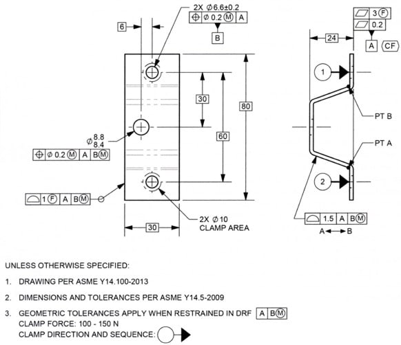
Please ref to the figure below, two questions need help:

1. Is it valid to have a Free-State symbol within the flatness FCF? Since the restraint note on the drawing will override the Free-State default condition, so I will say No, am I right?
2. What's the meaning of the 2nd segment flatness callout?

2020-06-22_114334_cd3hw0.jpg


Thank you for the help

Season
 
Replies continue below

Recommended for you

JP,

As far as I'm concerned, a feature is any surface or group of surfaces that is identifiable. FOS is a subset of that. As usual the committee works hard to make work miserable for everyone else.

1.3.27 Feature
feature: a physical portion of a part such as a surface,
pin, hole, or slot or its representation on drawings, models,
or digital data files.

How is a pin, a hole, or a slot identified? Is it a group of surfaces? Can a datum feature be multiple pins or multiple holes? Seems like there is no pluralization in the definition of 'feature'. Is it the empty volume of a hole that is the feature or is it defined by the single surface, which is redundant with the first part of the definition?

Why do you think I would find them mutually exclusive?
 
yet completely unnecessary for everything except features of size

The use of <CF> has been expanded in 2018 not because its a frivolous way to do the same thing as other established controls but because I think the committee realized it is a useful way to intuitively communicate the design intent to treat a collection of features/interrupted feature as a single feature - regardless of FOS or nonFOS.

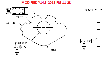
In addition, when applied to nonFOS use of <CF> can do things which profile alone cannot necessarily do. Consider the below modification of Y14.5-2018 fig 11-23 (apologies for the roughness, I did it very quickly to show a CF application where the individual features as well as the resulting continuous feature are nonFOS). Without the <CF> symbol and instead say "nX" notation for a pattern I'm not sure it would be necessarily required that the dynamic profile tolerance zone for each arc progress in the same direction or with the same magnitude as the others. Use of <CF> makes this clear.

modified_CF_xnrpdc.png


This all said, I found a strange portion of Y14.5-2018 inside one of the paragraphs devoted to dynamic profile. At the end of para 11.10.3 (Dynamic Profile Tolerance Applied to the Lower Segment of Multiple Single-Segment Feature Control Frames) there is the verbiage which reads "NOTE: Multiple features are considered to be a single feature unless “INDIVIDUALLY” follows a separate single-segment profile feature control frame." The accompanying figure is 11-37 which deals with, as the title suggests, a dynamic profile tolerance in the lower segment of a MSS FCF.

I'm not sure how one should interpret this. I don't think the purpose was to undermine the use of <CF> - in fact I think it would be detrimental to consider by default multiple features with a profile tolerance as a single feature, and use of INDIVIDUALLY would be conflated between its true use (breaking a pattern) and this suggested use (breaking a single implied continuous feature).

Something tells me there is an error here that was missed. I am interested in everyones thoughts on this.
 
3DDave said:
Why do you think I would find them mutually exclusive?
Simply because of your second post in this thread. You recounted that the definition of the CF symbol mentions only features and not FOS. That seemed to imply that you see features as not including FOS.

Certainly there are distinctions between the two ("directly toleranced," etc.) but I mildly disagree with textbooks (Krulikowski) that treat the word "feature" as 100% interchangeable with "surface."
For the record, I am fine with CF on any feature that meets the general requirements of the symbol's intent. Thankfully the 2018 standard is a bit more clear about that.

John-Paul Belanger
Certified Sr. GD&T Professional
Geometric Learning Systems
 
chez311,

In Fig 11-23, I think the grouping mechanism for the 0.4 dynamic profile is the <CF> symbol. In Fig 11-37 I think the grouping mechanism for that 0.4 dynamic profile is the all around symbol. So, I agree that the note at the end of 11.10.3 is a mistake. I think deleting that note would be a good change.

The work to be done with grouping affects the 2 mm profile of a surface specifications in both figures also. Since profile of a surface can control coplanarity and also stepped parallel planar surfaces, I don't think features such as those shown in Figures 11-23 and 11-37 can be said to not have similar feature relationship control. Since no explicit rule is provided for the coplanarity or co-stepularity (;-)) control, that assertion will not come without opposition. The good news is that grouping should be greatly clarified and improved in the next version of Y14.5. The bad news is the time we all have to wait until that next revision will be released.

Burunduk,

Regarding "saturation point of equivalent tolerancing" and some other comments you made, I think you opinion is unusual, given the completely unanimous vote for <CF> with flatness my informal polling has found over the past 10 years (workplace polling, not committee meeting polling). If we are to have any equivalent methods at all, some will say that we don't need this one or that one. If we want to impose a "no equivalent tolerances" rule, I'd personally be OK with that, but it would mean a lot of changes, and it would result in specs with fewer symbols, appearing simpler on first glance possibly, but really just the same level of complication specified using less intuitive specs, I believe.

I think we all want the simplest and also the most intuitive language, but depending on the definition of "simplest" those two traits can compete with each other. I think being more intuitive is more important than being simple.

One reason I think we should delete all other boundary names other than MMC, LMC, MMB and LMB is that it would be both simpler and more intuitive if we made that change. I also think it would address both objectives if we get rid of having two interpretations for tolerances specified at MMC or LMC. That would have to be considered a new topic though, so I will restrain myself :) (my opinion regarding which interpretation to delete does not match the current majority).

Dean
 
Dean,

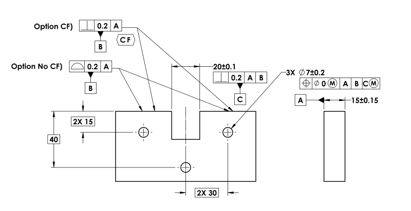
Could you, please explain a little further your idea about orientation controls (perpendicularity) with CF?

 
It is really interesting to see a thread that started with a question about tolerancing in free state but turned into a discussion about continuous feature and then about dynamic profile tolerance zone modifier ;-)

Regarding application of the continuous feature, <CF>, modifier to non-features of size... I am in the camp saying that there is nothing wrong with that when Y14.5-2009 is in charge. I agree with Dean that it is more intuitive to apply flatness with <CF> than profile to control coplanarity, but let's be honest - the way it was defined in 2009 is very far from perfectly clear. This and many other discussions here and in other GD&T forums just prove that.

As for Burunduk's comment that <CF> is completely unnecessary for everything except features of size... Well, couldn't the same* effect be accomplished by applying datumless zero at MMC position tolerance to the features considered as elements of the continuous feature?

Regarding chez311's comment that if 'nX' was applied instead of <CF> to the profile callouts in his modification of figure 11-23/2018, he would not be "sure it would be necessarily required that the dynamic profile tolerance zone for each arc progress in the same direction or with the same magnitude as the others. Use of <CF> makes this clear"... If the agreement is that in fig. 11-37 the all-around symbol assures that all surfaces progress collectively, then why in the modified fig. 11-23 the 'nX' wouldn't assure that too?

* Same in terms of geometrical requirements but different from measurement data reporting practices point of view.
 
pmarc,

You make a good point, the grouping of features with all-around or all-over does throw some complications into the mix. What about when we consider another case of multiple patterned features controlled with profile, say if Y14.5-2018 fig 11-37 was instead a pattern of 2X features (similar to 11-26) would you expect the dynamic profile tolerance zones to progress together?
 
chez311 said:
You make a good point, the grouping of features with all-around or all-over does throw some complications into the mix. What about when we consider another case of multiple patterned features controlled with profile, say if Y14.5-2018 fig 11-37 was instead a pattern of 2X features (similar to 11-26) would you expect the dynamic profile tolerance zones to progress together?

Yes, from the consistency perspective this is what I would expect, unless INDIVIDUALLY is used, as mentioned in the note you questioned.
 
pmarc,

In that case lets take it a step further. Take my same hypothetical case, say we want to override the requirement for the dynamic profile tolerance to progress together but not the nX pattern on the lower segment which holds the features of the pattern in relative location/orientation. I'm not sure one could apply INDIVIDUALLY and expect to accomplish this, I would expect such notation to also break the pattern that holds the features in relative location/orientation. I don't think this is a contrived requirement - we regularly specify patterns of rFOS such as holes and expect them to satisfy their requirements for size independently while still maintaining relative location/orientation of all the features in a pattern.
 
Perhaps this just proves that the standard is missing one more level of "grouping" mechanism.
 
Is it "missing" when no one has made a case for a functional reason to do so?
 
Dean,
Consider a pattern of holes, perhaps used as a secondary datum feature on the part, controlled for position at MMC with reference only to the flat face which the holes are drilled normal to.

Many people are confused by this because position with reference to a datum is associated with location relative to that datum, and here we only control orientation to the DRF and mutual location+orientation between the holes.

For the sake of intuitiveness, let's allow to replace the position symbol with the perpendicularity symbol. That way it will be clear to everyone what type of relationship is expected between the considered features and the datum reference, and since the number of places (nX) specification is listed as a pattern creating mechanism, everyone will know that the holes must be mutually located within the tolerance zones. This will make the life of "suppliers with marginal GD&T knowledge" much easier, wouldn't it?

If we don't mind for form or orientation tolerances to control mutual location (coplanarity) when used with CF, why is there an issue with the mutual location of holes being controlled by perpendicularity when applied on a pattern?

Again, a bad idea.

Every concept becomes "intuitive" once understood. Expanding the standard on and on in to introduce more intuitiveness for people who don't fully grasp the basics doesn't make sense. Instead of creating an unbearable abundance of different tools and conflicts between general principles and special cases, make the definition of existing tools more rigorous, concise, and accessible.
 
A perpendicularity tolerance establishes a single tolerance zone.

How would multiple, not-coaxial, separate holes fit into a single tolerance zone in order to establish location relative to one another?

On the other hand, would multiple, nominally co-axial bores to accept a pin be allowed to controlled with a single perpendicularity tolerance when modified with CF? Seems like that would be a single feature being controlled by a single tolerance.
 
Burnuduk,

The comparison is between perpendicularity with CF vs. profile applied to the two surfaces that are defined as datum feature B. Perpendicularity is more intuitive than profile, I believe.

It is more intuitive because it is exactly the same tolerance needed if there was no notch in the middle of the part. No need to change to profile, just because a notch interrupts the feature.

That's the way I see it anyway. I am not going to bet on you agreeing on this one :)

Dean
 
Dean, pmarc

Would you agree that if Y14.5 were to allow using CF in the way proposed by Dean (see above) that CF in ASME would be some sort of CZ ISO's equivalent?
And then why not extend its usage to runout?

(I know CZ could be okay to be used with orientation controls as well runout)
 
3DDave said:
A perpendicularity tolerance establishes a single tolerance zone.

Based on what?
Just because the standard doesn't show other examples?

Consider a pattern of holes with position tolerance and an orientation refinement, not by the means of a composite feature control frame, but a perpendicularity second segment. The perp. second segment would create as many tolerance zones as the nX notation specifies. The tolerance zones would not be locationally constrained to each other unlike in the case of composite position because orientation controls do not locate features - mutually or to a DRF.

Dean,
The above example, specifically the difference between the two refinement options also shows why we shouldn't have an orientation control controlling coplanarity. Coplanarity = mutual location between different surfaces. The fact that a symbol is used that tells the drawing user to "imagine" that two separated surfaces form a single planar feature and that he "only" evaluates the orientation of that imaginary single surface doesn't change that fact.
 
That's "n" single tolerance zones. Position allows for a group under the "Simultaneous" DRF rule.

The use of CF over-rides the concept of "different surfaces" by explicitly stating that they are s single surface for purposes of applying the tolerance. An orientation control controls coplanarity of all individual elements of the single surface it's applied to. Why would you think otherwise?
 
Coplanarity of elements of a single surface is actually the form - more specifically flatness of that surface.
You can virtualize a single planar surface by "treating" two surfaces as one for the purpose of applying the tolerance but that is really nothing but letting in a location control (of features relative to each other) through the back door, because the single surface is a fiction. You are just calling usual things by names that are not intended to describe them. Why do that when you have another option and that is applying a characteristic that is intended to locate (among its other uses)?

 
Also, the gist of my perpendicularity example* wasn't to suggest it might work with the current definitions, but to show that not everything "intuitive" should be pushed into the standard.

Edit: *this is in the context of the original "proposal" to Dean to let perpendicularity applied on a pattern co-locate features.
 
Status
Not open for further replies.

Part and Inventory Search

Sponsor