Continue to Site

Eng-Tips is the largest engineering community on the Internet

Intelligent Work Forums for Engineering Professionals

  • Congratulations SDETERS on being selected by the Eng-Tips community for having the most helpful posts in the forums last week. Way to Go!

ISO Equivalency

Status
Not open for further replies.

Kedu

Mechanical
May 9, 2017
193
I'm trying to grasp ISO concepts and I would like to clarify some on my (most likely) misunderstandings:

A hole is dimensioned for size and location:
Ø40 ± 0.1 E (envelope requirement)
pos Ø0.05 (circle X) to A primary, B secondary and C tertiary

is the above scheme equivalent with

Ø40 ± 0.1 GX
pos Ø0.05 to A primary, B secondary and C tertiary


On the same token:

A pin is dimensioned for size and location:
Ø40 ± 0.1 E (envelope requirement)
pos Ø0.05 (circle N) to A primary, B secondary and C tertiary

Could its (pin's) definition also be written as:

Ø40 ± 0.1 GN
pos Ø0.05 to A primary, B secondary and C tertiary

Thanks for any input and corrections your might offer.

 
Replies continue below

Recommended for you

These are not equivalent schemes.

One of the differences would be that in the scenario with the envelope requirement for size and with circle X(N) for position, maximum straightness error of the extracted median line of the hole (shaft) would be controlled by the size tolerance, whereas in the other scenario position tolerance would limit the extracted median line of the hole (shaft).
 
Pmarc,

I will not be myself if I would not try to comment/learn on/from this post:
Should I understand that the maximum straightness error of the extracted median line is controlled by the position (in the second scenario where position is RFS) because of the value being 0.05 or because GX/ GN modifiers applied to the size allows it? In other words, I am asking if the size tolerance would have been 0.01 (instead of 0.2 shown) what is controlling the maximum error of the extracted medina line?

Never seen on my prints (with my limited ISO exposure) GX or GN and let alone "X"-es or "N"’s in the position, concentricity or symmetry. But that is my fault by sticking in my little world.

Thank you again pmarc


In the "pos Ø0.05 to A primary, B secondary and C tertiary" scenario the maximum straightness error of the extracted median line is limited by the position tolerance value.

GN or GX modifiers mean that the given size requirement applies to the minimum circumscribed or maximum inscribed associated cylinders.
 
Thank you pmarc and greenimi

May I ask some additional questions:

I know that the bonus tolerance within ISO is not quite the same as the ASME’s one (size of the unrelated actual mating envelope is “THE SIZE” which determine the bonus).

In ISO what size is to be used to get the correct value for the bonus?

What I do understand is that in order to get the bonus I have to do a subtraction between maximum material size MMS and *a* measured size but I could not comprehend what size should I use.

Does a feature of size has a single measured value? My answer: I do not think so.

Therefore, some confusion arise. I am sure the confusion IS NOT within the ISO standards, but in my lack of ISO education.

That is why I was asking in my original post about GX and GN and their equivalency (or lack thereof) with X and N modifiers because I would like to get the same effect of the ASME’s (UAME size) bonus. I know X and M modifiers (or N and M modifiers) could not be combined in the same callout (position/ concentricity/ symmetry) because of different ISO interpretation of the axis versus surface (no axis interpretation when M is shown).

pmarc said:
For example, circle X modifier used in a position tolerance frame applied to a hole changes default controlled element from imperfect extracted median line to a perfect axis of the maximum possible cylinder expanded within the hole. So it defines the same requirement as position callout in ASME.

Circle N modifier used in a position tolerance frame applied to a pin changes default controlled element from imperfect extracted median line to a perfect axis of the minimum possible cylinder contracted about the pin. So again, it defines the same requirement as position in ASME.


I am trying to understand why these modifiers cannot act like ASME's UAME and how to apply the bonus, if needed, in ISO.
 
ISO does not use bonus tolerance concept at all because location and orientation tolerances applied at MMR and LMR basis can only be interpreted in terms of surface of the feature.

When circle X or circle N modifier is defined in the position tolerance indicator, it makes the requirement working similar to position at RFS in ASME, but ISO 1101:2017 is pretty specific - these modifiers cannot be combined with material condition modifiers, i.e. circle M or circle L in one callout. See para. 8.2.2.2.2.

And one more thing worth to mention: ISO explicitly states that use of location or orientation tolerances at MMR or LMR in conjuction with a size callout subject to the envelope requirement usually leads to superfluous requirements regarding function (assembleabilty) of the feature, and that use of such constraints reduces technical and economical advantages of MMR and LMR concepts. See ISO 2692:2014, para. 4.2.1 Rule C, note 2 and para 4.3.1, Rule J, note 2. This is something that ASME has been misteriously silent about.
 
pmarc 30 May 19 15:27 said:
And one more thing worth to mention: ISO explicitly states that use of location or orientation tolerances at MMR or LMR in conjuction with a size callout subject to the envelope requirement usually leads to superfluous requirements regarding function (assembleabilty) of the feature, and that use of such constraints reduces technical and economical advantages of MMR and LMR concepts. See ISO 2692:2014, para. 4.2.1 Rule C, note 2 and para 4.3.1, Rule J, note 2. This is something that ASME has been misteriously silent about.

Sorry to derail an ISO discussion but I'm curious - if we're to put this in ASME terms, are the "superfluous requirements" mentioned due to the additional deviation allowed at MMC (for example, position deviation) requiring perfect form due to rule 1 (envelope principle) when in reality further size/form deviation up to the virtual condition would potentially result in an acceptable part? This would be the reason for the suggestion to utilize zero positional tolerance at MMC in section 7.3.4 in Y14.5-2009 (10.3.4 in 2018), right? What is it that you believe ASME has been silent about?
 
And one more derailment (or sort of)
Interesting….ISO does not use the bonus concept.

Are you saying that the tolerance zone SIZE won’t change with each size of the feature? So what is happening between MMS and LMS with the tolerance zone? Stays the same? (I am trying to use the terminology I’ve seen used in this discussion and maybe something I know from ASME, but I realize I might be wrong about this verbiage)

Or maybe is even wrong talking about the size of the tolerance zone, isn’t it?
ISO is a different “animal” altogether.


greenimi said:
Are you saying that the tolerance zone SIZE won’t change with each size of the feature?

Don't worry, it will. They just don't call it "bonus"


"For every expert there is an equal and opposite expert"
Arthur C. Clarke Profiles of the future

 
Does anyone has a paper/document that they can post to explain for beginners (people like me) the "bonus concept " in ISO?

I was trying to read, and most important understand, ISO 2692 with no much success due to the fact is referencing other standards (14405-1, 14660-2, 5458, 17450-1) which I don't have access to and nor the required knowledge.

Thank you


chez311 said:
Sorry to derail an ISO discussion but I'm curious - if we're to put this in ASME terms, are the "superfluous requirements" mentioned due to the additional deviation allowed at MMC (for example, position deviation) requiring perfect form due to rule 1 (envelope principle) when in reality further size/form deviation up to the virtual condition would potentially result in an acceptable part? This would be the reason for the suggestion to utilize zero positional tolerance at MMC in section 7.3.4 in Y14.5-2009 (10.3.4 in 2018), right? What is it that you believe ASME has been silent about?

What I mean is that Y14.5 is full of examples of features controlled with:
- size requirement subject to Rule #1, and
- position or orientation tolerances at MMC (or LMC) of values different than zero,
yet it doesn't seem to mention (as far as I can tell) that in such cases this combination might impose unnecessarily restrictive set of requirements from functional (assembly) standpoint.

Zero position tolerance at MMC (or LMC) indeed addresses the issue, but I hope you will agree that there are applications where zero position tolerance at MMC isn't always desired.

greenimi said:
And one more derailment (or sort of)
Interesting….ISO does not use the bonus concept.

Are you saying that the tolerance zone SIZE won’t change with each size of the feature? So what is happening between MMS and LMS with the tolerance zone? Stays the same? (I am trying to use the terminology I’ve seen used in this discussion and maybe something I know from ASME, but I realize I might be wrong about this verbiage)

Or maybe is even wrong talking about the size of the tolerance zone, isn’t it?
ISO is a different “animal” altogether.

I am saying that in ISO there is only one interpretation of location and orientation tolerances at MMR or LMR. It is the surface interpretation, so what really matters is that the surface of the feature doesn't violate maximum material virtual condition (MMVC) boundary or least material virtual condition (LMVC) boundary. Therefore, since there is no axis interpretation of location and orientation tolerances at MMR or LMR, there is no need to think about these tolerances in terms of tolerance zones (and their growth in size), and therefore there is no need to use the concept of bonus tolerance at all.
 
So, you are checking ONLY for the virtual condition boundary? Well, probably yes, because the same thing you are doing in ASME, don't you?

For example in the OP case (and adjusted with my extended question for MMR clarification):
a hole is dimensioned for size and location:
Ø40 ± 0.1 GX
pos. Ø0.05 (M) to A primary, B secondary and C tertiary

the MMVC to be checked is 40-0.1-0.05 = 39.85

and the local size should be the maximum inscribed cylinder and this cylinder's size to be between 39.9 and 40.1. No local size (point to point caliper measurement) in the traditional sense to be verified?
Am I correct?

 
Checking virtual condition all alone is not enough, because how do you know mating part is not oversized/undersized (just like in ASME)?
Here is an exapmle with measured values, where you can benefit from size tolerance, benefit from "zero position", etc.
In fact, ISO has additional tool called "reciprocity" - you may do either - adjust geo tolerance at the expense of size tolerance or adjust size tolerance at the expense of geo tolerance.
They just don't call it "bonus"

"For every expert there is an equal and opposite expert"
Arthur C. Clarke Profiles of the future

 
 https://files.engineering.com/getfile.aspx?folder=143548e6-ef34-4b06-b8b5-6e8b654e1035&file=Position_Zero.png
Of course, you are not only checking virtual condition. You are also checking the size limit that is on the "opposite side" to the virtual condition. I thought that was obvious.
 
pmarc 30 May 19 18:03 said:
yet it doesn't seem to mention (as far as I can tell) that in such cases this combination might impose unnecessarily restrictive set of requirements from functional (assembly) standpoint.

Isn't this essentially what 7.3.4(2009) and 10.3.4(2018) says? From a selection of 2018 paragraph 10.3.4 :

"However, rejection of usable parts can occur when these features of size are actually located on or close to their true positions but are produced to a size smaller than the specified minimum (outside of limits). The principle of zero positional tolerancing at MMC allows the maximum amount of tolerance for the function of assembly."

pmarc 30 May 19 18:03 said:
Zero position tolerance at MMC (or LMC) indeed addresses the issue, but I hope you will agree that there are applications where zero position tolerance at MMC isn't always desired.

I would tend to agree, how then does ISO's MMR concept accomplish this? It sounds like it is fundamentally different than ASME's MMC.
 
From ISO 2692:2014:

"When maximum material requirement, MMR, or least material requirement, LMR, is used, the two
specifications (size specification and geometrical specification) are transformed into one collective
requirements specification. The collective specification concerns only the integral feature, which in this
International Standard relates to the surface(s) of the feature(s) of size(s).

[...]

4.2.1 Maximum material requirement for toleranced features
The maximum material requirement for toleranced features results in four independent requirements:
— a requirement for the upper limit of the local size [see Rules A 1) and A 2)];
— a requirement for the lower limit of the local size [see Rules B 1) and B 2)];
— a requirement for the surface non-violation of the MMVC (see Rule C);
— a requirement for when more than one feature is involved (see Rule D)."


Notice that nowhere does it mention a requirement for the size of UAME-kind of thing or any other similar unrelated entity.
 
chez311 said:
Isn't this essentially what 7.3.4(2009) and 10.3.4(2018) says? From a selection of 2018 paragraph 10.3.4 :

"However, rejection of usable parts can occur when these features of size are actually located on or close to their true positions but are produced to a size smaller than the specified minimum (outside of limits). The principle of zero positional tolerancing at MMC allows the maximum amount of tolerance for the function of assembly."

No, that is not it. The quote applies rather to the situations that the picture provided by CH depicts (imagine that it is for ASME). Per the conventionally toleranced illustration, pin having actual size of for example dia. 60.1 located close to its true position would have to be rejected because of size non-conformance. However, from assembly perspective it would be well functional - because it would not violate the vitual condition of dia. 60.3. Therefore it makes sense to open up upper tolerance for the pin size and change the position tolerance from 0.3 to zero at MMC

What I am trying to say (what ISO says) is that for requirements like:
pin dia. 60 0/-0.4
|pos|dia. 0.3(M)|A|B|
Y14.5, by having default Rule #1, requires the pin to not violate the perfect form at MMC boundary of dia. 60.0, whereas from functional point of view (assembly in most cases) there is usually no need to have this requirement imposed.
 
pmarc said:
pin dia. 60 0/-0.4
|pos|dia. 0.3(M)|A|B|
Y14.5, by having default Rule #1, requires the pin to not violate the perfect form at MMC boundary of dia. 60.0, whereas from functional point of view (assembly in most cases) there is usually no need to have this requirement imposed.

So, In ASME you have to do 3 checks:
60 envelope (ring gage)
local size 59.6 - 60
AND
another "envelope" of 60.3 (ring gage)

ISO says: get rid of one of the envelopes: most likely 60 envelope.

Is my understanding correct?

Now, what about if GN is added to the size? how these checks are to be modified?
 
greenimi said:
So, In ASME you have to do 3 checks:
60 envelope (ring gage)
local size 59.6 - 60
AND
another "envelope" of 60.3 (ring gage)

ISO says: get rid of one of the envelopes: most likely 60 envelope.

Is my understanding correct?

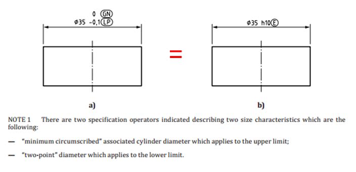
Yes, your understanding is correct. To invoke the requirement for dia. 60 envelope, circle E modifier or combination of (GN) and (LP) modifiers would have to be added to the size callout. Something like on the picture below:
capture_vwuxgs.jpg


greenimi said:
Now, what about if GN is added to the size? how these checks are to be modified?

GN modifier added to the size callout means that the size of the minimum associated cylinder circumscribed about the actual (extracted) integral feature shall be within 59.6-60.0. I would say this technically creates incomplete size specification because nothing controls how small the actual local sizes of the cylinder can be.
 
What I am trying to say (what ISO says) is that for requirements like:
pin dia. 60 0/-0.4
|pos|dia. 0.3(M)|A|B|
Y14.5, by having default Rule #1, requires the pin to not violate the perfect form at MMC boundary of dia. 60.0, whereas from functional point of view (assembly in most cases) there is usually no need to have this requirement imposed.

I am trying to think of a case that would warrant the 60.0 upper limit on local size (ISO), but not on circumscribed cylinder size (ASME). I haven't come up with anything so far. Can anyone provide an example?


pylfrm
 
Status
Not open for further replies.

Part and Inventory Search

Sponsor