Continue to Site

Eng-Tips is the largest engineering community on the Internet

Intelligent Work Forums for Engineering Professionals

  • Congratulations SDETERS on being selected by the Eng-Tips community for having the most helpful posts in the forums last week. Way to Go!

ISO Equivalency

Status
Not open for further replies.

Kedu

Mechanical
May 9, 2017
193
I'm trying to grasp ISO concepts and I would like to clarify some on my (most likely) misunderstandings:

A hole is dimensioned for size and location:
Ø40 ± 0.1 E (envelope requirement)
pos Ø0.05 (circle X) to A primary, B secondary and C tertiary

is the above scheme equivalent with

Ø40 ± 0.1 GX
pos Ø0.05 to A primary, B secondary and C tertiary


On the same token:

A pin is dimensioned for size and location:
Ø40 ± 0.1 E (envelope requirement)
pos Ø0.05 (circle N) to A primary, B secondary and C tertiary

Could its (pin's) definition also be written as:

Ø40 ± 0.1 GN
pos Ø0.05 to A primary, B secondary and C tertiary

Thanks for any input and corrections your might offer.

 
Replies continue below

Recommended for you

pin dia. 60 0/-0.4
|pos|dia. 0.3(M)|A|B|

Pmarc,

Wouldnt the addition of a straightness tolerance within 0.3 at MMC to your above example provide approximately what you are describing? Ie: override requirement for perfect form at MMC but maintaining the VC boundary at 60.3 due to nonzero position tolerance with MMC size of 60?
 
Chez311,
Is your latest question from today at 01.46 talking about ISO or ASME?
Because the entire discussion has been on an ISO stuff😜
 
Kedu,

I am aware. My latest question is just trying to understand whether the effect of ISO's MMR can be approximated with ASME's MMC somehow, as well as understand better how exactly ISO's MMR behaves. As I said before, I apologize for the slight derailment, I hope you are not displeased with the sidebar discussion.

(Edit: though to be fair there are several sidebars....)
 
pmarc said:
“GN modifier added to the size callout means that the size of the minimum associated cylinder circumscribed about the actual (extracted) integral feature shall be within 59.6-60.0. I would say this technically creates incomplete size specification because nothing controls how small the actual local sizes of the cylinder can be.”


So, you are saying that only GN is not enough? I was under the impression that GN will control the global size of the pin.

Also, in order to control the local size GN along with ACS, ALS or SCS should be used. That is what I am seeing in ISO 14405-1: 2017 table 3 page 23 (which I purchased recently).

So, my understanding is (and here I might need your help to correct if I am wrong):

If only GN is shown that is the direct global size
For the local sizes to be invoked you need GN with one of the operators above (ACS, ALS or SCS)
Why am I saying this: because all local sizes are shown with ACS, ALS, or SCS in the table 3.

What am I missing?

Thanks


Chez311,
Don't worry. Move along. I'm interested too.
 
chez311,
I think the addition of a straightness tolerance within 0.3 at MMC to this example would be an approximation, but I would see at least one problematic thing here. Per ISO lack of the envelope requirement in the callout means that size tolerance doesn't control any aspect of form of the feature. And in consequence it means that maximum possible straightness and circularity errors of the pin would rather depend on the dia. 60.3 MMVC.

I am not sure the same applies in ASME. In other words, I am not sure that overriding Rule #1 by straightness at MMC callout overrides cross-sectional requirement for perfect circularity of the pin when at MMC. This has been a point of contention for a long time even amongst very reputable members of the Y14.5 committee.

-----

Kedu,
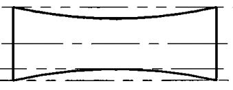
Yes, I am saying that GN alone is not enough. As you said, this is global-size type of requirement therefore it doesn't control all necessary aspects of the size of the feature. Imagine this kind of shape:

capture_gshcl2.jpg


Size callout with GN modifier will only control how big/small the envelope circumscribed about that external feature can be, but it will not have a power over controlling the depth of the saddle. As I showed in my previous illustration, to fix the problem a combination of GN and LP modifiers would have to be used (if you really wanted to use GN modifier) or just circle E modifier.
 
pmarc 31 May 19 20:41 said:
I am not sure the same applies in ASME. In other words, I am not sure that overriding Rule #1 by straightness at MMC callout overrides requirement for perfect circularity of the pin in each cross-section.

You mean perfect circularity at MMC size, I guess? How nuanced a difference is there between requiring perfect circularity and the actual limit of size at MMC, if that makes sense?
 
Yes, I meant perfect circularity at MMC. I edited my post a minute before I saw your reply.
 
Pmarc,

I guess I'm still wondering about the same thing though, requiring perfect circularity at MMC and requiring that it meets the size tolerance at MMC seem very similar if not almost identical. Perhaps there's some nuance that I'm missing.
 
Let me try to explain what I meant.

Some people think that with the application of the DML straightness tolerance at MMC, let's say of 0.3, to the shaft of the diameter 60 0/-0.4, each circular element of the shaft is allowed to occupy dia. 60.3 circular boundary, meaning that when all actual local sizes in a single cross-section are equal to MMC size, there is still a room for a circularity error.

There is, however, another group saying that with the application of the DML straightness tolerance of 0.3 at MMC, each circular element of the shaft must not violate dia. 60.0 circular boundary, i.e. they believe that the DML straightness tolerance only deals with the straightness error, but has nothing to do with what goes on in cross-sections.

I hope you will agree with me that the difference between the two approaches isn't just nuanced.
 
Pmarc,
Is it something to do with ambiguous definition of the actual local size in ASME?

Also is this problem valid in ISO or just Y14.5?

 
It is not the first time in the last week or so where a thread ends up in the "circularity controversy court"

A few years ago a master thread has been run by pmarc

This week another thread

got stuck in the same place.

Just to help a little bit: has been concluded on other discussions that there is a conflict between 5.4.3- ASME Y14.5-2009 and 2.3.1/Y14.5.1-1994 (Math Standard). No figure in Y14.5 that shows clearly how the "no rule#1" / Independency principle cancel rule#1 requirement in the individual cross section.

Now, in the meantime two new developments could affect this conundrum:
(I said COULD, but I am not sure it WOULD)

1.) Releasing of ASME Y14.5-2018. Is this new standard offer any good clarification? I doubt that, otherwise pmarc would mention it, correct?

2.) New draft for math standard which is not released yet, but was under the public review lat few months or so. This new math standard has been worked on especially for supporting the 2009 version of Y14.5 or dedicated for 2009 so to speak. Also, the same request, would be nice if someone would confirm that the conflict I mentioned above has been eliminated.

Just my 2 cents.
 
pmarc 31 May 19 22:08 said:
Some people think that with the application of the DML straightness tolerance at MMC, let's say of 0.3, to the shaft of the diameter 60 0/-0.4, each circular element of the shaft is allowed to occupy dia. 60.3 circular boundary, meaning that when all actual local sizes in a single cross-section are equal to MMC size, there is still a room for a circularity error.

pmarc,

I had a hard time discerning exactly what you were talking about until I read the threads greenimi posted (thank you greenimi). By "all actual local sizes in a single cross section" are you referring to 2 point measurements of size? For example 2 point local measurements of size combined with circularity error that would produce the lobed shape that CH refers to in the thread ( in his post on (6 May 13 11:23)?

I was going on the definition posed by Y14.5.1-1994 that greenimi also referenced (section 2.3.1). I do not believe this definition would allow variation (at least not such variation which would allow each circular element in your example to occupy a diameter of 60.3 which is greater than its MMC size of 60.0) such as the lobed shape posited by CH in that thread since the definition of size in Y14.5.1-1994 relies on sweeping spheres along the feature, not two point measurements.

pmarc 31 May 19 22:08 said:
There is, however, another group saying that with the application of the DML straightness tolerance of 0.3 at MMC, each circular element of the shaft must not violate dia. 60.0 circular boundary, i.e. they believe that the DML straightness tolerance only deals with the straightness error, but has nothing to do with what goes on in cross-sections.

I agree with this interpretation. Even if we assumed straightness could say something about each individual cross section, per my above any variation which violated a 60.0 circular boundary would also violate its size tolerance per Y14.5.1-1994, at least thats the way I read it.

Additionally, how does ISO interpret size compared to Y14.5.1 ?

greenimi 1 Jun 19 18:57 said:
Just to help a little bit: has been concluded on other discussions that there is a conflict between 5.4.3- ASME Y14.5-2009 and 2.3.1/Y14.5.1-1994 (Math Standard).

greenimi/pmarc,

Also not sure how these two sections conflict each other, or where such conflict is mentioned in the referenced threads. In fact 5.4.3 in Y14.5-2009 is largely a restatement of 6.4.3 in Y14.5.1-1994.

However, greenimi - in your post in ( on (26 Apr 19 11:39) theres a presentation which suggests the Y14.5.1 draft includes both a definition for size of circular elements (essentially the same swept spheres I mentioned previously which are in the currently release Y14.5.1-1994 that are sliced by a cutting plane perpendicular to the spine) as well as a provision for opposing points (2 point measurement). I'll have to check the draft I have later today but I don't see why they would present two opposing definitions.
 
greenimi, chez311,

Yes, this has a lot to do with actual local size definition in Y14.5.

Limits of size definition given in para. 2.3.1 in Y14.5.1M-1994, which is based on swept-spheres concept, indeed doesn't allow the circular elements to go beyond the circular boundary of MMC size (also beyond the circular boundary of LMC size), and that's a deciding argument that those who think that a DML straightness at MMC may affect allowable circularity of the cylindrical feature are incorrect.

But this also means that addition of a DML straightness at MMC requirement to a combination size and position at MMC callout on an ASME-based drawing, as suggested by chez311, doesn't produce the same set of requirements as a combination of size (with default lack of envelope requirement) and position at MMC in ISO. It's because in ISO default interpretation of a linear size callout is two-point local size only, therefore there is no reason why a cylinder with all actual two-point sizes equal to MMC couldn't still have a certain amount of circularity/roundness error, like a tri-lobe shape. 

Another problem with the swept-spheres based Y14.5.1M-1994's definition of limits of size (not mentioned in this discussion yet) is that when the Independency modifier (I) is added to the size callout of a cylindrical feature of size, the limits of size definition causes that the (I) modifier isn't able to release all aspects of form error, as it should, in my opinion. In other words, while straightness error gets indeed released by the application of (I) modifier, the circularity error must still not be larger than the size tolerance, which is kind of against what independency of size and form means to me (and to ISO). Just a thought.
 
Limits of size definition given in para. 2.3.1 in Y14.5.1M-1994, which is based on swept-spheres concept, indeed doesn't allow the circular elements to go beyond the circular boundary of MMC size (also beyond the circular boundary of LMC size), and that's a deciding argument that those who think that a DML straightness at MMC may affect allowable circularity of the cylindrical feature are incorrect.

In fact, the new draft adds clarity for when rule #1 is not in effect (2.3.2.2). As far as I can tell there is no loosening of allowable circularity tolerance, only in form/straightness of the DML (spine of swept spheres). This would be my assumed interpretation of the current Y14.5.1-1994 swept spheres definition of size tolerance, but is now intended to be explicitly stated.

in ISO default interpretation of a linear size callout is two-point local size only, therefore there is no reason why a cylinder with all actual two-point sizes equal to MMC couldn't still have a certain amount of circularity/roundness error, like a tri-lobe shape.

Another problem with the swept-spheres based Y14.5.1M-1994's definition of limits of size (not mentioned in this discussion yet) is that when the Independency modifier (I) is added to the size callout of a cylindrical feature of size, the limits of size definition causes that the (I) modifier isn't able to release all aspects of form error, as it should, in my opinion. In other words, while straightness error gets indeed released by the application of (I) modifier, the circularity error must still not be larger than the size tolerance, which is kind of against what independency of size and form means to me (and to ISO).

I'm not sure if we need the independency modifier in ASME to achieve a functionally equivalent result. If we take your initial example:

pin dia. 60 0/-0.4
|pos|dia. 0.3(M)|A|B|

If we interpret this per ISO without the envelope principle it would allow a lobed pin I mentioned previously - that is two point measurements of 60.0 all around but a lobed form deviation which if measured by a circumscribed circle/cylinder has size 60.3 - right? I agree that it does not produce the same exact set of requirements, but how is this functionally different than if we instead changed the callout to the below and interpreted it per ASME even with the envelope principle in place?

pin dia. 60.3 0/-0.7
|pos|dia. 0(M)|A|B|

This still allows a pin with any combination of size/form deviation when measured by a circumscribed circle/cylinder is limited to 60.3 - however in this case instead of requiring the form to be lobed to achieve that it can actually be fully circular/cylindrical, in this case the ISO requirement would actually be tighter! I'm not really sure that this is a "problem" in the ASME interpretation and I'm not sure of any advantage ISO has in the 2-point measurement vs. ASME swept spheres. Why would you want a lobed pin with circumscribed size 60.3 when a cylindrical pin of the same size would do fine?


Side note: I consulted the Y14.5.1 draft I have on had, while it adds definition of "Actual Local Size" to the current "Limits of Size" section it actually specifically states that these measurements of "Actual Local Size" (2-point and circular elements) are not necessary requirements (in fact it utilizes the word "estimate" in the circular elements note) and do not supercede/replace the requirement for conformance to the swept spheres interpretation. I assume these were added to provide methods of measuring local size to estimate conformance.
 
chez311 said:
I'm not sure if we need the independency modifier in ASME to achieve a functionally equivalent result. If we take your initial example:

pin dia. 60 0/-0.4
|pos|dia. 0.3(M)|A|B|

If we interpret this per ISO without the envelope principle it would allow a lobed pin I mentioned previously - that is two point measurements of 60.0 all around but a lobed form deviation which if measured by a circumscribed circle/cylinder has size 60.3 - right? I agree that it does not produce the same exact set of requirements, but how is this functionally different than if we instead changed the callout to the below and interpreted it per ASME even with the envelope principle in place?

pin dia. 60.3 0/-0.7
|pos|dia. 0(M)|A|B|

This still allows a pin with any combination of size/form deviation when measured by a circumscribed circle/cylinder is limited to 60.3 - however in this case instead of requiring the form to be lobed to achieve that it can actually be fully circular/cylindrical, in this case the ISO requirement would actually be tighter! I'm not really sure that this is a "problem" in the ASME interpretation and I'm not sure of any advantage ISO has in the 2-point measurement vs. ASME swept spheres. Why would you want a lobed pin with circumscribed size 60.3 when a cylindrical pin of the same size would do fine?

What if all actual local two point sizes of the pin were LMC = 59.6 and the actual pin was a tri-lobe? That would be fine according to ISO, but it would fail the swept-spheres based ASME definition, wouldn't it?

So yes, I agree we don't need the independency modifier in ASME to achieve equivalent result. We need the independency modifier AND something that would override the requirement for containment of the surface of the feature between two half-spheres of MMC and LMC diameter and impose pure two-point size instead.
 
What if all actual local two point sizes of the pin were LMC = 59.6 and the actual pin was a tri-lobe? That would be fine according to ISO, but it would fail the swept-spheres based ASME definition, wouldn't it?

Agreed. Towards MMC (diameter of local size spheres per ASME from 60.0 to 60.3) the ASME scheme accepts functional parts and the ISO scheme rejects functional parts. Towards LMC (actually past LMC per ASME - diameter of local size spheres per ASME from 59.6 to 58.9 with 2 point measurements of the cross section no less than 59.6) the ASME scheme rejects functional parts while ISO accepts them.

Acceptance of these previously rejected functional parts could be allowed if the ISO scheme was changed to read the same as the ASME one ie: 60.03 +0/-0.7 and 0 position tolerance @ MMR but without the envelope requirement. Now the ISO scheme would be more lenient across the board.

As to whether equivalency in this regard is actually "needed" - I don't know.
 
Pmarc and chez311,
If bonus tolerance is not applicable in ISO, I would like to ask: what about regardless of a feature size RFS? Is this term used in ISO?

What would be the equivalent of outer boundary and inner boundary ASME's terms in ISO?

Using the same example as before

pin dia. 60 +0/-0.4
|pos|dia. 0.3 |A|B|

but I removed MMR from the position.


Good question Kedu - pmarc would have to answer that. I'm just getting a handle on how ISO interprets MMR.

I'm going to go out on a limb here based on the conversation so far, and pmarc can correct me here if I'm wrong, but it seems that even in the absence of invoking the envelope principle or any other form control - with MMR in ISO there is a boundary of perfect form at the feature's virtual condition (in this case 60.3 in the initial example with MMR). With RFS, or whatever the ISO equivalent is, I wonder if there is a similar requirement at the feature's outer boundary, or if an additional form control would be required to invoke such a boundary.

Actually thinking about it further, does applying the independency symbol in ASME still create a similar boundary at virtual condition? I think with RFS position and independency would definitely place no such limit on form, but I'm not sure Y14.5 really deals with the MMC case and its relation to virtual condition. It seems to me that even with independency applied with MMC there is still a boundary of perfect form that cannot be violated at the feature's virtual condition - I think it has to in order to still properly evaluate MMC position/orientation and bonus tolerance. This is probably the reason that Y14.5 states MMC DML straightness cannot be larger than the specified orientation/position tolerance - in fact it goes so far as to explicitly state in the 2018 version in 8.4.1.3 that MMC DML straightness additionally "does not contribute to the IB or OB of the position or orientation tolerance" since by definition straightness overrides rule #1.
 
kedu said:
If bonus tolerance is not applicable in ISO, I would like to ask: what about regardless of a feature size RFS? Is this term used in ISO?

What would be the equivalent of outer boundary and inner boundary ASME's terms in ISO?

Using the same example as before

pin dia. 60 +0/-0.4
|pos|dia. 0.3 |A|B|

Let me try.

pmarc, Please feel free to shut down any of my comments as I am speaking into the ISO language (a language I am still learning)

I do not thing think regardless of a feature size is a term used in ISO!!! Risky assumption for my part....I know.
The equivalent of outer and inner boundary is: worst case boundary. Hmm, that is what I got from some training material is ISO I got.

worst case boundary for the example is 60+0.4= 60.4.
Now, the question is: What is the global size for this pin?

pmarc,
If MMR has been removed, then wouldn't the feature/ drawing become incomplete? No envelope requirement, no form requirement.
I assume we should add now circularity and straightness of this pin in order to have a complete definition.
Am I missing something?

As usually, ISO beats me hard.


To add a little bit, just for my own edification I would ask:
- What would be the design cases where using:
Size with E envelope + position RFS
versus
Size with no E envelope + position modified at MMR

When one versus the other is the correct description of the design intent?

Looks like both of them will create the same value of worst case boundary or maximum material virtual condition, hence my applicable question.


Status
Not open for further replies.

Part and Inventory Search

Sponsor