Continue to Site

Eng-Tips is the largest engineering community on the Internet

Intelligent Work Forums for Engineering Professionals

  • Congratulations SDETERS on being selected by the Eng-Tips community for having the most helpful posts in the forums last week. Way to Go!

ISO Equivalency

Status
Not open for further replies.

Kedu

Mechanical
May 9, 2017
193
I'm trying to grasp ISO concepts and I would like to clarify some on my (most likely) misunderstandings:

A hole is dimensioned for size and location:
Ø40 ± 0.1 E (envelope requirement)
pos Ø0.05 (circle X) to A primary, B secondary and C tertiary

is the above scheme equivalent with

Ø40 ± 0.1 GX
pos Ø0.05 to A primary, B secondary and C tertiary


On the same token:

A pin is dimensioned for size and location:
Ø40 ± 0.1 E (envelope requirement)
pos Ø0.05 (circle N) to A primary, B secondary and C tertiary

Could its (pin's) definition also be written as:

Ø40 ± 0.1 GN
pos Ø0.05 to A primary, B secondary and C tertiary

Thanks for any input and corrections your might offer.

 
Replies continue below

Recommended for you

First of all, my apologies for the slow reply. Too much going recently and probably in future months.

I don't see Regardless of Feature Size (RFS) term used in ISO GPS standards. Also, I can't find in any ISO standard that I have access to anything about terminology for what ASME calls Outer Boundary (OB) and Inner Boundary (IB) for geometrical tolerances at RFS. I did see, however, some ISO-based training materials where their authors - mostly coming from the US - used these terms.

I agree that in absence of the envelope requirement and any form control for a feature of size controlled with location or orientation tolerance at MMR, the maximum material virtual condition (MMVC) becomes the boundary that indirectly limits the feature's form variation. However, if the feature is controlled with location or orientation tolerance at RFS (using ASME terminology), the situation becomes tricky, in my opinion, mostly because it is much more difficult to properly calculate the size of the worst-case boundary of the feature.

For example, if we assume that the worst (resulting in extreme size of the outer boundary) shape of the as-produced feature, say shaft, is a tri-lobe with actual local sizes equal to maximum material size (MMS), then we will face the problem of determining how big the unrelated outer boundary for that shape can be. One of ISO GPS books I have says that for a perfectly straight tri-lobe the size of the outer boundary can be up to approximately 115% of MMS. So in our example it would approximately be 1.15 x 60 = 69. That unrelated shape would be additionally allowed to wander 0.15 (0.3/2) in each direction from the theoretically exact position or have the extracted median line error of 0.3, and this would give the OB of dia. 69.3.

This answer is probably satisfactory in most of practical use cases, but I am not sure that in theory a tri-lobe is really the worst-case shape (from the outer boundary size standpoint). So, to greenimi's question about incomplete drawing specification, I am leaning towards saying that the combination of dia. 60 0/-0.4 & |pos|dia. 0.3|A|B| is indeed incomplete callout (although I wouldn't say that there is no form requirement at all - in ISO position tolerance controls straightness of the extracted median line of the feature).
 
pmarc said:
I don't see Regardless of Feature Size (RFS) term used in ISO GPS standards.
This naturally made me curious - what happened?

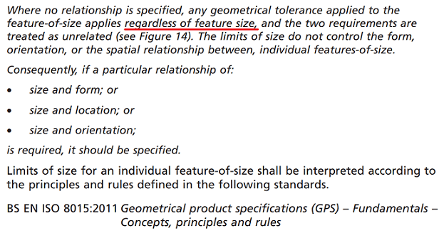
You could see mention of RFS in older edition of ISO 8015:
Capture1_wzc1wg.png

Interestingly it is seen as equivalent of independence principle, which applies by default anyway.

Even with 1985 edition obsolete, you could see RFS mentioned in BS8888:
Capture2_vkj7pe.png

Having the same meaning: geometrical tolerances and size tolerances are unrelated unless explicitly specified otherwise.

One could imagine with recent clean-up ISO decided to get rid of redundant requirement.
Also, as geometrical controls apply independently from size there is no need in any magical "boundaries" as well (unless specified otherwise).

Interestingly, in ASME, in absence of (M) or (L) RFS applies which means all geometrical controls are subject to independence principle by default. (But going there would be hijacking the thread :))

"For every expert there is an equal and opposite expert"
Arthur C. Clarke Profiles of the future
 
Even if ISO no longer refers to the default requirement as RFS - I have to assume that there are rules which govern what happens when MMR or LMR do not apply, correct?

Interestingly, in ASME, in absence of (M) or (L) RFS applies which means all geometrical controls are subject to independence principle by default.

I've already asked a few questions about ASME rules so I don't think thats out of the realm of whats already been discussed. I think understanding the differences between each helps me form a more complete understanding of both. I'm curious, could you explain why you think independency applies by default on RFS applications? I'm assuming you mean something more nuanced than what it seems on the surface, because at face value I disagree with you but perhaps you are talking about independency of the geometrical control vs. independency applied to the size tolerance? I'm a little confused.

Also interested if anyone has any input on my earlier question (6 Jun 19 15:33) - for ASME it seems to me pretty clear cut that independency applied to RFS position places no limits on the inner/outer boundary (unlimited variation of form) without additional form controls. However, with independency applied to MMC/LMC position (without any other form controls) it seems like, similar to ISO, there should still be a boundary of perfect form at virtual condition.
 
CH,
I re-read your post. I agree that by default RFS means the size tolerance applies independently of the geometrical control, however the term "Independency" and related (I) symbol has a specific meaning in ASME in that it removes the requirement of perfect form imposed by the envelope principle/rule #1. I assume that you are referring that the former applies by default (size tolerance applies independently of the geometrical control) and not the latter (RFS is the same as applying the Independency "I" symbol).


However, if the feature is controlled with location or orientation tolerance at RFS (using ASME terminology), the situation becomes tricky, in my opinion, mostly because it is much more difficult to properly calculate the size of the worst-case boundary of the feature.
{...]
So, to greenimi's question about incomplete drawing specification, I am leaning towards saying that the combination of dia. 60 0/-0.4 & |pos|dia. 0.3|A|B| is indeed incomplete callout (although I wouldn't say that there is no form requirement at all - in ISO position tolerance controls straightness of the extracted median line of the feature).

pmarc,
So it seems that ISO has some general rules when "RFS" applies, however it seems like such ambiguity (and per CH's note removing references to RFS in the standards) is to push the designer to either apply MMR/LMR controls and/or explicitly apply form controls.
 
@chez311:
Well, I didn't go as far as attacking (I) symbol exactly for the reason you mentioned - you may need it to explicitly override perfect form at MMC principle. Should (I) symbol be explicitly applied to size then? Y14.5 places it "next to the appropriate dimension or notation" which is a bit blurry.

"For every expert there is an equal and opposite expert"
Arthur C. Clarke Profiles of the future

 
Well, I didn't go as far as attacking (I) symbol exactly for the reason you mentioned - you may need it to explicitly override perfect form at MMC principle.

I'm not so sure it would even with MMC. Independency (I) would remove the requirement for perfect form at MMC size but not at the virtual condition dictated by the geometric control, at least thats my interpretation. This is similar to the ISO interpretation (no envelope by default, still boundary of perfect form at MMVC).

As a restatement of my previous post: This is probably the reason that Y14.5 states MMC DML straightness cannot be larger than the specified orientation/position tolerance - in fact it goes so far as to explicitly state in the 2018 version in 8.4.1.3 that MMC DML straightness additionally "does not contribute to the IB or OB of the position or orientation tolerance" since by definition straightness overrides rule #1.

Should (I) symbol be explicitly applied to size then? Y14.5 places it "next to the appropriate dimension or notation" which is a bit blurry.
I would say it should be applied to the size tolerance. Rule #1 applies to the size tolerance, not the geometrical control - so if one wishes to cancel out rule #1 with the Independency (I) symbol it should then be placed next to the size. I agree the "or notation" part makes it fuzzy though.
 
Genuinely curious if anyone has any input into my inquiry about ASME MMC. It seems to me that the Independency (I) symbol would remove the requirement for perfect form at MMC size dictated by rule #1, but there would still be a boundary of perfect form at virtual condition dictated by the geometric control at MMC (in this case position). This would differ from a geometric control at RFS applied to a feature of size, the Independency symbol (I) would allow unrestricted form deviation in the absence of any other form control.
 
Chez311,
In ASME ( and maybe in ISO too) the virtual condition boundary ( or the MMVC in ISO) wouldn't have BY DEFINITION a perfect boundary? As far as I understood this VC condition is creating a material free zone which the hole could not violate. So, I would say that regardless if I is used or not the same free material zone is enforced.
 
ASME Y14.5-2018 said:
virtual condition: a constant boundary generated by the collective effects of a considered feature of size’s specified MMC or LMC and the geometric tolerance for that material condition.

Kedu,

The above is the definition of virtual condition per the 2018 version (the 2009 version is very similar, I just think this is more clearly worded). It doesn't mention how it should be interpreted when perfect form is not required at a FOS specified MMC or LMC size. It is definitely a "material free zone" as you say, however the way I imagine the interrelationship of the "feature of size’s specified MMC or LMC and the geometric tolerance" is the displacement of a feature of perfect form at MMC/LMC displaced the amount allowed by its geometric tolerance such as is shown by the series of figures starting with Y14.5-2009 2-12 (or 5-14 for 2018). Perhaps that just a mental though process or paradigm thats holding me back and I should just take the calculation for virtual condition at face value, ie: for MMC virtual condition its just MMC size - applied geometric tolerance for an internal feature. I think the only way we can interpret this virtual condition boundary at MMC/LMC is a perfect, constant boundary unaffected by the Independency (I) symbol. Otherwise I think calculation of bonus tolerances falls apart and MMC/LMC loses its meaning.
 
Chez311, CH, pmarc

Pmarc said:
I don't see Regardless of Feature Size (RFS) term used in ISO GPS standards. Also, I can't find in any ISO standard that I have access to anything about terminology for what ASME calls Outer Boundary (OB) and Inner Boundary (IB) for geometrical tolerances at RFS. I did see, however, some ISO-based training materials where their authors - mostly coming from the US - used these terms.

If RFS is not applicable in ISO on the controlled area of the feature control frame then I would like to ask what about the datum reference frame section on the FCF?
Is RFS term used there or it is forbiden /removed from ISO nomenclature too?


And what could be the reason(s) that ISO decided to remove RFS from their specified modifiers in the first place? Did they change their concept of location / orientation controls applicability?
 
Status
Not open for further replies.

Part and Inventory Search

Sponsor