Continue to Site

Eng-Tips is the largest engineering community on the Internet

Intelligent Work Forums for Engineering Professionals

  • Congratulations IDS on being selected by the Eng-Tips community for having the most helpful posts in the forums last week. Way to Go!

ISO GPS - Position of Surface to Datum A

Mech1595

Mechanical
Oct 16, 2023
36
All,

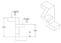
Below is a grossly oversimplified model, as I can't share the original I received from a customer. Customer print is to ISO GPS.

For Datum Features A2 & A3, they have a position specified with respect to [A]. Is this valid?
I know that position to a surface is valid in ISO, I'm just not sure about the reference to [A], as those features are part of what defines [A].

1736869701096.png
 
Replies continue below

Recommended for you

I think in ISO the A1, A2, A3 are used for datum target points, lines etc. Not sure what is currently shown on your drawing is correct.
ISO5459-2011 could be a good resource for you and for your customer.

Ask THE CUSTOMER what is the DESIGN intent.
 
Not sure what is currently shown on your drawing is correct.
ISO5459-2011 could be a good resource for you and for your customer.
Thanks for the reference, I'll see if I can get a copy to review. We primarily work with Y14.5, so ISO prints always cause me some pain.

The odd thing is in another view (top), they do have A1, A2, & A3 defined with circular datum target areas (actual part has thru-holes on those tabs for fasteners), but then show exactly what I have drawn above.
 
See this discussion


Part and Inventory Search

Sponsor