Eng-Tips is the largest engineering community on the Internet

Intelligent Work Forums for Engineering Professionals

Keep axis parallel and in same plane with GDT? 1

Status
Not open for further replies.

Oaklandishh

Mechanical
Sep 3, 2014
48
0
0
US
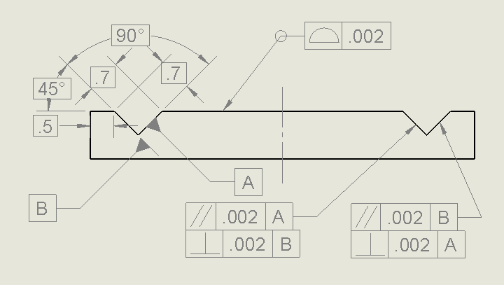
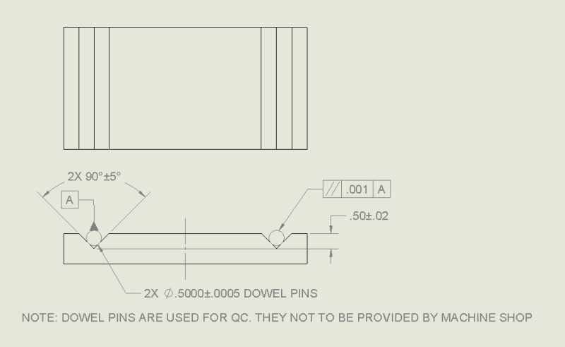
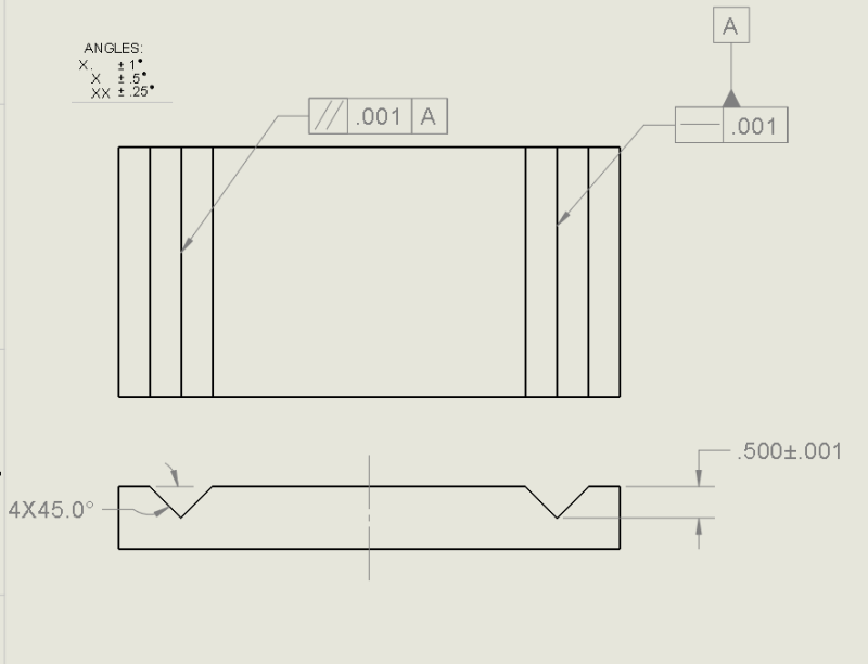
Assuming I have a double V block part as shown below, and the design intent is to keep the axis of the two imaginary cylinders lying in the part parallel and in the same plane, what is the best way to do this?

AOM3kBe.png


I have some ideas as to how to make this happen (below), but I am unsure as to how I would actually QC the parts in real life.

VBlockDrawingExample_piv18r.png
 
Replies continue below

Recommended for you

Oaklandishh,

I would not use an inside corner as a datum feature. I woudl use the two sides of the v-groove as datums[ ]A and[ ]B, respectively. How does your inspector demonstrate that the corner of your v-groove is at .500[±].001? This is a good case for profile tolerances. The second v-groove faces must be parallel and perpendicular to datums[ ]A and[ ]B.

You can make the two grooves parallel. Making the centre to centre distance absolutely precise will be way more challenging.

--
JHG
 
So Something more like this?

The Profile Dimensions the first slot where the datums as well as loosely dimensioning the other slot are and the parallel and perpendicular are used to refine the other slot relative to the datums?
VblockDrawingExampleV2_uv2frd.png


I assume I would check the parallel and perpendicular callouts using the datums A and B notch clamped on a gage block and then just running a dial gage on the other slot's surfaces?
 
Oaklandishh,

I'd recommend an approach that more closely matches the imaginary assembly you describe. Here's a possibility:

In the end view, use phantom lines to show one of the imaginary cylinders as a circle tangent to the flat surfaces of the V-groove. Attach a datum target symbol to the circle. Specify the basic diameter of the cylinder in the top half of the symbol, and assign an identifier (I'll use "A1" for this example) in the bottom half.* This will establish a datum axis that can be used to constrain two translational and (more importantly) two rotational degrees of freedom.

To control relationship of the second V-groove to datum axis A, you have some options. A standard method would be to apply a parallelism tolerance (referencing datum A) to each of the flat surfaces, or better yet, to a small portion of each surface that will include the contact line.

Alternately, you could show the second cylinder as a circle just like the first, give it a basic diameter dimension, and apply a parallelism tolerance referencing datum A to create a cylindrical tolerance zone of the required diameter. Applying a parallelism tolerance to an imaginary cylinder isn't exactly standard-compliant, so you should probably explain the intention with a note.


*For a related example, see datum target A2 in Fig. 4-49 of ASME Y14.5-2009.

pylfrm
 
Pylfrm,

I've done just that with the requirement that tooling gage rounds and spheres be used. I'd rather control the desired outcome directly than put up with a big stack that is hard to evaluate. For example, in the above diagram, it hardly matters what the included angle of the faces are - 70 to 135 would probably be just fine and no need for each groove to have the same included angle.

 
Controlling the relationship of two V's in a part is important in many of the parts where I work.

I tend to use something along the lines of what's already been mentioned, except the angles of the V's are always important on my parts. In my case, I use profile of a surface to control the second V relative to the first.
 
The Angular control you were looking for was a problem because the sloped surface elements were already parallel to the bottom surface. What you were looking to control was their perpendicularity to the side faces.

If one were to take any planar faced wedge and cut at random angles, perpendicular to one face and forming parallel sides, then the faces would remain with parallel elements just as they were before the cut. All that has changed is the addition of sides that one face might not be perpendicular to. Since one face, by definition, is already perpendicular, it leaves the other face open to be misaligned to the cut surface.
 
Relating to Pylfrm and 3DDave's comments. Is this an acceptable thing to do?
PinQC_mpypcg.png

I am at a small company, so I do the QC as well as the drawings, I would much rather have something easy to QC.

Parallel implies parallel and planar correct?
 
I strongly second the application of tooling balls/gage pins for use in verifying the parts. This reminds me most of a sine plate or sine bar so I'm going to approach it with that frame of mind.

Your last drawing looks best, to me, in post dated 07SEP2016-15:28.

What I would do: specify an appropriate flatness on the base surface (opposite the grooves). Dimension from that flat surface to a line tangent to the tops of both gage pins with +/- .001 or w/e is appropriate. This controls the depth of the vee-grooves without concern as to the location of the actual vertex, as your dimension is doing. This is especially important when you don't really care about the angle, which, if your +/- 5deg is true; you don't care much. You could constrain the orientation of the gage pin centerlines as being both parallel to eachother, and parallel to the base surface. The numbers may or may not differ, but it establishes the plane they must stay on, and also controls the allowable taper relative to eachother.

This makes it easy to check, as you can rest the part on a surface plate with the "vees up" and check it with a height gage, test indicator, and/or other simple gage tools on-hand. It is also likely pretty close to the parts actual functional requirements.
 
Oaklandishh,

Tolerancing an assembly like you've shown is indeed acceptable, but it has some disadvantages. Now you have to worry about various possible form errors in the dowel pins for your tolerance analysis. Such form errors can also lead to disagreement between inspections using different pins. This is why I suggested using imaginary perfect cylinders and the datum target notation. It certainly does shift some burden to the inspection side though, so you'll have to judge the trade-off.

In any case, you should probably consider specifying how the cylinders shall be held in the V-grooves, and any additional requirements needed to ensure stability or repeatability.

Also, in the parallelism feature control frame of your latest drawing, the tolerance value should be preceded by a diameter symbol. This will create a cylindrical tolerance zone for the cylinder axis and control both rotational degrees of freedom (parallel and planar to use your terminology).

Unless it's functionally relevant, I'd recommend against involving the base surface in the parallelism tolerances. An inspection of the pins alone shouldn't be too difficult with a surface plate, height gage, and test indicator. One option would be to place the part upside down on top of the pins, using riser blocks as needed. The setup could then be rotated to place one pin above the other for inspection of the other degree of freedom. Pins somewhat longer than the grooves will make this easier.

I agree with JNieman on the point about not tolerancing the location of the groove vertex.


pylfrm
 
Status
Not open for further replies.
Back
Top