Continue to Site

Eng-Tips is the largest engineering community on the Internet

Intelligent Work Forums for Engineering Professionals

  • Congratulations KootK on being selected by the Eng-Tips community for having the most helpful posts in the forums last week. Way to Go!

L-L interface control

shvet

Petroleum
Aug 14, 2015
681
Dear forummembers

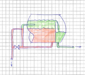
Is here anybody familiar with such L-L level control scheme? Is this method workable or not?
 

Attachments

  • L-L.png
    L-L.png
    1.3 MB · Views: 8
Replies continue below

Recommended for you

Hi,
This is not going to work; you will carry forward light phase with heavy phase.
You must disconnect the light phase pipe.
Pierre
 
Last edited:
Err sorry, but where exactly is inflow as both pipes just flow out?

What are you trying to do?

Densities of liquids involved here?

Is valve open or closed?

Any level control or instrumentation?

Give us something more to work on here please.
 
Little inch,
it is very clear ! this is a LL separator.
bottom valve is closed , open only to drain the separator.
Green is light phase , red is heavy phase .
The interface is controlled by the height of the inverse U pipe .
Pierre
 
Hi,
This is not going to work; you will carry forward light phase with heavy phase.
You must disconnect the light phase pipe.
Pierre

Disconnect from light liquid (green) and connect to vapor space (white). The same as for G-L level control? Am I correct?
What if the horizontal run of U-pipe will be oversized so velocity is almost 0? Will it help to avoid carryover?
 
Little inch,
it is very clear ! this is a LL separator.
bottom valve is closed , open only to drain the separator.
Green is light phase , red is heavy phase .
The interface is controlled by the height of the inverse U pipe .
Pierre
Not when there is no inflow it isn't.

But I agree it won't work because if there was more green stuff than shown, it would just flow out of the pipe on the left.
 
Shvet.
Block the light line, no connection to the vapor space.
Only heavy phase going through the inverse u pipe. Of course the valve is closed.
Little lunch,
When liquid at rest, nothing special. the phase will separate.
Pierre
 
Shvet.
Block the light line, no connection to the vapor space.

If U-pipe is not connected to the separator then U-pipe elevation will have nothing to deal with L-L interface in the vessel. Am I correct?
The highest point of U-pipe can be 1 meter higher or 1 meter lower and this won't affect L-L level. Or I do not catch something?

@LittleInch
This is the classical continious 3-phase separator for chem industry. The difference (for me personally) is the weird methods to control L-L level. I have not met such U-pipe for L-L application and the contractor denies to provide a detailed comment.

As an example see the picture
 

Attachments

  • Example.png
    Example.png
    68.6 KB · Views: 5
Last edited:
The U-bend will not act as a Wier. It will act as a siphon. Even if it acted as a wier, it would not control interface level. It would behave the same as the other wier, controlling liquid level.
 
I'm very familiar with a 3 phase separator and this is not one.

I agree, the LL interface level control is not going to work.
 
A description and explanation are given in Perry's chemical Engineer's handbook - page 15-26 -7th edition
To prevent siphoning effect the upper part of the inverse U should be connected to the vapor space/vent. No connection between the Inverse U leg and the light phase.
Pierre
 
Last edited:
A schematic with equation.
In your case ZL is the height of the weir .
Pierre
 

Attachments

  • separator shvet.pdf
    24.5 KB · Views: 4
Found
A description and explanation are given in Perry's chemical Engineer's handbook - page 15-26 -7th edition
A schematic with equation.
In your case ZL is the height of the weir .
Thank you very much, Pierre. That is exactly what I need.

for info, not for reply
Actually my concerns are related to LL densities. Densities difference is small ~20 kg/m3 or 2% and those are variable/unstable. I would not post such issue if this was similar to a hydrocarbon-water separator.
 
Last edited:
There are many other variations. Preconditioning of the feed to minimise emulsion formation is key to prevent cross contamination due to emulsions.
 
Definitely the low difference of density is a key parameter together with the height of the heavy drain leg. A sensibility analysis of those parameters has to be done.
Instead of using a fixed head ZH, I would advise to install an adjustable leg. This is my experience with mixer settlers for the separation of rare earth (10 years).
To answer to George, for emulsion, the keys parameters are the residence time, the ratio Heavy to light materials, the viscosity of the phases (temperature). Coalescers of different types and materials will help the separation.
Note: Your separator must be equipped with sight glasses for operators to visualize the position of the interface.
If your phases have different conductivities, an online analyzer is going to help.
Good luck
Pierre
 
The 2nd diagram @shvet posted is not the same as the 1st sketch. The 2nd diagram is relatively better.

What is the L-L coalescer used in the 2nd diagram - a knit wire mesh pad or a tilted cross flow plate pack or some other?
 

Part and Inventory Search

Sponsor