Eng-Tips is the largest engineering community on the Internet

Intelligent Work Forums for Engineering Professionals

Limiting Hole to Hole Size Variation

Status
Not open for further replies.

JCReynolds79

Automotive
Sep 6, 2007
115
0
0
GB
Hi all,

Numbers of holes , equally spaced on a PCD. The size of the holes can be quite loose, say, +/- 0.2mm. But what I am trying to think of is a way to control the variation of hole sizes. In sentence speak, Holes can be +/-0.2 but each hole must be within 0.05 of each other.

e.g. dia 10 +/- holes specified gives a hole size target of 9.8-10.2. Lets say the first hole we make is 9.9. I want to ensure/control/specify that all other holes in the pattern must be within +/-0.05 of first hole. So all other holes must now lie within range 9.85-9.95.

Its like I want a composite tolerance on the hole size....

Thanks!

Regards,

Jon Reynolds
 
Replies continue below

Recommended for you


Jon,

I was about to post a link to this older thread as I remembered someone discussing a "slack" tolerance on here some time ago, however I realized that it was you who also posed that question. Scanning through that thread JP's reply jumped out to me especially since theres been much talk about the dynamic profile modifier lately, as it has now been implemented in Y14.5-2018.

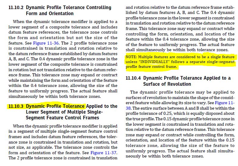
I was about to say that it wasn't clear dynamic profile would provide the control you desire, however I noticed this little note at the end of the dynamic profile tolerance section for MSS (11.10.3) stating "NOTE: Multiple features are considered to be a single feature unless 'INDIVIDUALLY' follows a separate single-segment profile feature control frame." At first blush, I would interpret this to mean that the intent is that the tolerance zones progress together UOS by "INDIVIDUALLY". Unfortunately, I think breaking this requirement with "INDIVIDUALLY" brings up some other issues, which is another can of worms.

This essentially is what you are asking for I think, with the added constraint of form that a profile tolerance will provide vs. directly toleranced size. You might also have some inspection considerations as well, as has been mentioned in some recent threads (ie: likely requires CMM to inspect, the CMM software must be able to handle it, etc..).
 
chez311,

Watch for the dynamic profile symbol. This appears to be a new feature of ASME[ ]Y14.5[‑]2018. There is no mention of it under Multiple Single-Segment Profile Tolerancing or on the symbol tables in the 2009 standard.

DynamicProfile_b1oyqo.png

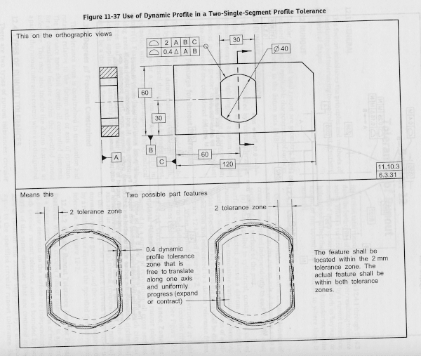
Here is the figure attached to the paragraph.

It looks like I can maintain an accurate but sloppily located complex feature. I can choose whether or not to control rotation by leaving out datums. I can apply it to a feature with multiple occurrences, but it would not control the sizes as the OP is asking.

--
JHG
 
drawoh,

I'm well acquainted with the dynamic profile modifier in Y14.5-2018 hence why I pointed it out and referenced the new standard. I know it wasn't in 2009, it is a new introduction for 2018.

See below for the section of Y14.5-2018 para 11.10.3 titled "Dynamic Profile Tolerance Applied to the Lower Segment of Multiple Single-Segment Feature Control Frames". I initially thought it wasn't clear it would do what OP asked, but then I read this note and it seems to suggest dynamic profile tolerance zones for multiple features tied together with some sort of pattern creation mechanism would indeed progress (expand/contract) simultaneously.

11.10.3_qbh7bm.jpg
 
chez311,

The OP wants to control variation of hole size. He does not care (much) what the size is, but they must all be the same. Dynamic profile controls the size accurately to the numbers I specify. That is not what the OP asked for.

--
JHG
 
It looks like I can maintain an accurate but sloppily located complex feature. I can choose whether or not to control rotation by leaving out datums.

Dynamic profile releases the constraint of size of a standard profile tolerance by allowing the tolerance zone to progress uniformly (expand/contract), but maintains the form tolerance requirements. The note I pointed out above seems to suggest that multiple features tied together with a pattern mechanism (ie: "nX" or "n COAXIAL HOLES") and a dynamic profile tolerance would also progress (expand/contract) simultaneously as if they were part of a single yet discontinuous feature. This would seem to satisfy OP's requirements. At least thats how I read it.
 
Yes, I read the note in the same way that you do. But because the dynamic profile tolerance without datums and with no INDIVIDUALLY added will also control spacing within the pattern, then I don't think this is the solution OP is looking for.
 
<off topic>

When scanning a document, placing black paper behind the page being scanned will eliminate the print-through from the ink on the opposite side.

There is plenty of light being reflected by the facing surface of the page and withheld by the ink on that same face to record the image of it. Backing with black paper captures the light that penetrates through the page and would otherwise come back except where it it absorbed by ink on the back side of the page.
 
Good point - and if INDIVIDUALLY is added, the way I read it the simultaneous progression would be broken as well so thats not what OP wants either.

I guess it could be used with the understanding that the location of the holes would be held tightly to within the form requirement dictated by the dynamic profile tolerance. And that size/form variations of one hole in the pattern would affect the position of that hole and others - for example if you had a 0.1 dynamic profile tolerance and you had one hole that came out to 25.1 and another to 24.9 they would BOTH be required to have perfect location.

Seems like it could be an overly tight requirement. In light of that and other reasons, I would probably recommend going with a note if one desired the behavior described by OP.
 
Yes, a note or a hybrid solution (dynamic profile FCF with a supplementary note worded such that the spacing requirement is cancelled) could probably work provided the intent is to control variation between MMB and LMB of the holes in the pattern. But if, for example, the design intent is to control variation of hole sizes understood as UAME sizes, then the dynamic profile approach may not work at all.
 
Hi All,

Interesting thread. Overall, I would say that the OP's requirement for "consistency of hole size" would best be specified in the form of a note. I had initially thought that Dynamic Profile might work, but there are too many unresolved issues in Y14.5's definitions for tolerances applied to multi-feature sets. This makes it very difficult to keep the "equal progression" aspect of multiple dynamic profile zones while turning off the default "mutual orientation and location" aspect.

chez311,

Don't get me started on the note in 11.10.3 ;^). The note just kind of comes out of nowhere, and imposes a special rule for one particular case (dynamic profile in a single-segment FCF). This is the type of thing that causes major headaches in Y14.5.1 when we try to write concise rules and mathematical definitions for Y14.5 characteristics. The note also creates direct conflicts with other Y14.5 content (the fact that the All Around symbol creates a pattern and not a single feature, and that the Continuous Feature <CF> tool is available for treating multiple surfaces as a single feature). I wish that the note had not been included.

Evan Janeshewski

Axymetrix Quality Engineering Inc.
 
Based on the OP's first paragraph my thought would be to call out the holes as follows:
DIA N +/-0.05
SEE NOTE 6

note 6 would read:

6 NOMINAL VALUE OF DIA N MAY VARY FROM 9.85 TO 10.15 FOR ANY INDIVIDUAL PART PROVIDED THAT ALL HOLES ON ANY PARTICULAR PART MEASURE WITHIN +/-0.05 OF THE AVERAGE OF ALL HOLES.


Peter Stockhausen
Designer / Checker
 
If they did the math first to solve well explained problems and then made explanations for general consumption, the explanation could be checked against the rigorous math, particularly for consistency. It would also mean CMM software creators could confirm compliant implementations and allow for concurrent release of the Dimensioning and Tolerancing standard and the Mathematical standard supporting it at the same time. Even the Geometric Dimensioning test (Where is "geometric dimensioning" defined in the standard?) would be ready for release.

Nothing better than a coordinated plan.
 
Using the average doesn't meet the OP "use the first hole" as a basis.

If the notion is to limit the range to 0.10, then the basing deviation from the average rejects parts with hole dimensions like 9.0, 9.0, 9.0, 9.0, 9.0, 9.09, while accepting 9.00, 9.02, 9.04, 9.06, 9.08, 9.10 and accepting 9.0, 9.0, 9.0, 9.1, 9.1, 9.1

 
Status
Not open for further replies.
Back
Top