Continue to Site

Eng-Tips is the largest engineering community on the Internet

Intelligent Work Forums for Engineering Professionals

  • Congratulations KootK on being selected by the Eng-Tips community for having the most helpful posts in the forums last week. Way to Go!

Lincoln Street Substation Transformer Explosion Burbank, CA - 04/10/2020 8

Status
Not open for further replies.

Mbrooke

Electrical
Nov 12, 2012
2,546
Transformer explosion and fire:


Looks like there was sustained arcing on the secondary before the explosion:


I'm guessing a short circuit occurred on the 12kv (or 16kv) side with relaying failing to catch/clear it. The transformer remained severally overloaded overheating to the point the oil inside it ignited.

I don't take credit for these picture but to give you an idea that power transformers typically contain anywhere between 7,000 to very well over 25,000 gallons of oil.


Can I make the claim that my practice of 200E fuses on the primary would have prevented all this? [afro2][clown]
 
Replies continue below

Recommended for you

Very interesting thread.
@oldfieldguy, @prc - I've seen a YNyn0 power transformer with the same paint "scorching" all along the tank due to induced currents, but it didnt developed into a fault, this effect showed after more than 20 years of service. I dind't even knew it could cause a failure. Sadly I don't have much information about the grounding or the load condition.

But back on topic:

My educated guess is that the LV bushings (located at the tank wall) breaked down because of the initial fire (you see smoke with the arcing) or the sustained dynamic forces. Once the oil started to leak it caught fire and the transformer exploded.
 
1) Find attached the paper I mentioned earlier.

2) As per a survey conducted on Transformer Fires by CIGRE,a couple of years back, probability of a fire is 0.1 % per service year ie one fire per 1000 transformers per year or 4 % probability in 40 year life.

3) Reason for Transformer fires can be summarized as below:
(a) Failure of HV OIP (oil impregnated condenser ) bushing - bushing failure cause shattering of porcelain due to entire system fault current going inside bushing) and released hot gases catch fire. Oil from main tank feed to fire.
(b)Failure of Line end OLTC (as in auto-transformers). Entire grid fault current flows releasing huge energy
(C) Failure in oil filled cable box on HV side
(d) Tank rupture from low impedance faults inside tank; long duration fault current flow through arc inside due to delayed breaker clearance.

Engineers have developed suitable mitigation measures ( dry RIP bushings; elimination of line end OLTC; avoid oil filled cable box; rupture resistant tank design; fast acting breakers etc, etc) Recent survey results from Australia shows that such mitigation measures are effective and have brought down transformer fires drastically in Australia.

 
 https://files.engineering.com/getfile.aspx?folder=cd934108-1dec-4397-9b19-35d0353ef908&file=2017-12-20-Prevention_of_Accidents_in_Distribution_and_Power_Transformers.pdf
FWIW, oldfieldguy might be either complimented or insulted at being called oilfieldguy... [blush]

CR

"As iron sharpens iron, so one person sharpens another." [Proverbs 27:17, NIV]
 
Not my question though- what happens if I short circuit the external secondary of an energized power transformer with no protection?


I saw the paper you linked, it speaks about failures common to the transformer itself.


Nowhere does it mention failure of protective relaying with an external short circuit.
 
Transformer fire normally is not due to any sustained fault on secondary side.

Normally. Typically. Everything you say is true for internal faults, tap changer faults, and bushing faults on the transformer itself.

However- It is not impossible for relaying to fail. Look at Astoria Substation in Queens where both the primary and secondary differential protection on a 138kv cable failed. It took several minutes for remote relaying to stop it.

In videos we see arcing external to the transformer itself going on for minutes:


This I think is key. Such external arcing would have triggered differential protection within cycles- seconds at most. Instead we see a violent external fault persisting.

The fact the transformer's zone (or busbar's zone) of differential protection did not trip shows failed protective relaying.


PRC said:
Your thinking long duration secondary fault will "boil" the oil inside the tank and it will start burning is simply not true. Remember Thermal time constant of an oil filled unit is 2-3 hours !

2-3 hours for a 135% overload. 40.5 MVA on a 30MVA unit. Heck I'm fine with 200%. 60MVA.

Now try an external short circuit. 100-237 MVA on that transformer.

237 MVA on a 30MVA FA unit is going to over heat the oil if left in that state indefinitely. The oil will get exceptionally hot, pressure will build, and it will start to smoke... Something is going to give...


Any arcing inside the transformer ( say from interturn faults) will not cause oil to catch fire though at the core of arc, temperature may be more than 3000 C ) Remember we were using oil as an arc quenching medium in oil circuit breakers !

Here we see arcing outside the transformer- and for minutes. Its blatantly obvious relaying had failed to trip breakers.

You can not convince me that 200MVA on a 30MVA unit will not start a fire by itself.

There was an incident at a Florida substation years back where a station service fuse blew, the batteries drained, and the relaying become inoperative. An external short circuit occurred on MV. It persisted and the transformer inside the station eventually exploded.

Honestly I think we need to be having a discussion why protective relaying is failing so often in electrical substations.
 
@prc-

Counting the two transformers that I had, one that burnt, one we caught before it burnt, I have seen one other, and it was a long time ago and details elude my memory, but it had recently been moved to a new location. A substation technician doing a routine station check noted excessive heat coming off it, a lot more heat than could be explained by the actual load. This transformer was taken out of service and scrapped as 'not worth the repair effort' due to its age. The utility company engineers surmised that something might have shifted internally during transport, but no effort was made to verify that theory.

The transformer I pictures above, as well as its mate, had no internal provision for mitigating stray flux. I've seen tanks lined with plated made of laminated steel, for instance. These were 10 MVA, apparently a pretty pedestrian design.

Operating parameters, as previously stated, were essentially balanced current load, since the major load was a 7000 horsepower VFD, and minor load, a 1 MVA station service transformer. The 'wild card' was that the incoming feed was residential/commercial feeder. We never did isolate a particular set of circumstances that produced the stray flux. It was not coincident with running the large motor, and the utility company was reluctant to release any real information about their conditions.

I've attached a picture of the second transformer, which we took out of service before it could progress to failure. The heat-discolored paint is obvious. Less obvious is that the PVC-jacketed flexible conduit was charred where it was in direct contact with the transformer case. I seem to recall that PVC chars at 250C, but can't point to a specific reference.

old field guy
 
oldfieldguy- apology for misspelling as oilfieldguy !
Thank you for all the details. It is true some times even for 10 MVA we may provide magnetic screen to reduce load losses ( not for any heating issues) esp when loss capitalization is high. If any tank heating occurs at full load, it would have come out at factory during heat run test. I concluded on zero sequence flux heating as you mentioned 5 limbed core as a solution for tank heating. Heating from stray flux will not come down by 5 limbed core.

The heating is seen on shorter side of tank. Was this there on longer side too? There were any two LV windings?

This issue of tank heating from zero sequence flux (it is not load dependent) can occur with operation with one phase fuse out. This is well explained in that 1978 presentation and later incorporated in a C57 standard on connections.

In India when we eliminated tertiary winding from all YNyn connected sub transmission units (220 or 132/33or11 kV- all our distribution transformers are Dyn connected) during mid 1970s, we were cautioned of tank heating by American utilities. Last 45 years thousands of 3 phase 3 limbed Ynyn connected units (up to 160 MVA) are working in our grid without tertiary windings. No case of tank heating from zero sequence flux reported so far. I was thinking this may be because we are using CB always for these transformers and hence no chance for operation with one fuse out.
Thanking you once again for giving details of this unique failure mode.

 
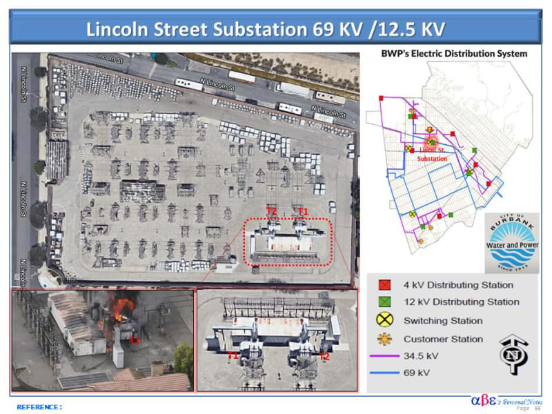
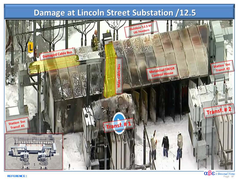
Here are a few days old images that unable to share in the forum until know.

Lincoln_St_Sub_No_1_r4dzkv.jpg


Lincoln_St_Sub_No_2_hzthmn.jpg
 
Gold star given, Epic work Cuky2000! [shadeshappy] Mad respect.


Looks like the arcing started/took place on the busduct?

 
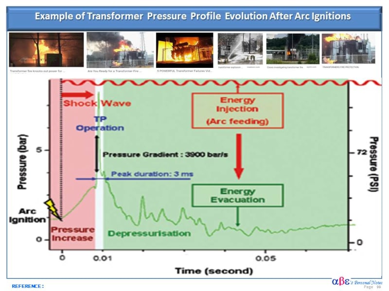
[highlight #FCE94F]QUESTION: There is a reliable and effective way to prevent similar catastrophic fires in transformers?[/highlight]
Transformer_-_Pressure_Profile_after_Arc_Fault_hujqgs.jpg
 
I'm still confused though- how does arcing on the bus duct cause arcing in the transformer?
 
A suggestion:
For whatever reason a fault caused an extreme heat buildup in the transformer.
The oil started boiling, but there was not enough oxygen to support sustained combustion inside the tank.
However oil vapour was released from the transformer and was burning externally.
The heat continued to build.
A winding failed, or an internal lead or connection failed, causing an internal arc.
The arc was fed by the grid capacity and was violent.
As happens with severe arcs, the oil and the oil vapour expanded explosively from the heat of the internal arc.
This is when the tank ruptured.
When the tank ruptured, the oil was released and as the oil may have been above the auto-ignition temperature, it ignited, either from the arc or from auto-ignition.
Probably from both.

prc:
Three legged cores versus five legged cores.
Is this correct or have I been led astray?
I was under the impression that a three legged core exhibited a strong phantom delta effect.
A five legged core does not exhibit a phantom delta, hence the addition of a delta winding.


Bill
--------------------
"Why not the best?"
Jimmy Carter
 
I would suggest that the short circuit capability of the transformer was exceeded. A transformer is, or should be, designed to carry a level of short circuit through current for a given time. If that value is exceeded, the internals of the transformer are going to fail, most likely starting with the windings. So now you have the short circuit inside the transformer. Next step is tank failure and so on.
 
@Waross- My money is on your suggestion.

A winding failed, or an internal lead or connection failed, causing an internal arc.

I think so now that you mention it. A half second before the tank exploded the intensity of the external arc appears to drop- possibly indicating a second internal fault developing within the transformer.

 
A moment of sober reflection.
A number of years ago one of our respected members lost some friends and co-workers in a transformer explosion.
We are sorry for your loss, friend.

Bill
--------------------
"Why not the best?"
Jimmy Carter
 
waross,
"Three legged cores versus five legged cores.
Is this correct or have I been led astray?
I was under the impression that a three legged core exhibited a strong phantom delta effect.
A five legged core does not exhibit a phantom delta, hence the addition of a delta winding."
You are correct. My understanding was also like that. But in US certain peculiar operating conditions can occur that will cause extreme tank heating for short periods as found by oldfieldguy. Please see page 22-25 of attached paper. Also C57.12.70-2011. Here also tank heating is due to tank becoming phantom delta. But the flux volume is so huge intense heating can occur.
 
 https://files.engineering.com/getfile.aspx?folder=0a3cb061-e6f6-4e5b-ab64-f2af3d19094d&file=7801-_Distribution_Trf_Application_Considerations_-_Westinghouse_-Pwr_Sys_District_Engrs_Conf.pdf
It is virtually impossible to make a specific accurate prediction of the cause of failure without a sequence of events and forensic data from the field.

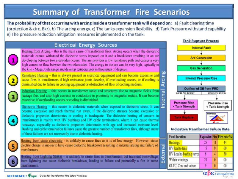
It is generally accepted throughout the power industry that the most probable cause of transformer fires is listed in the sketch below. This includes the heated effect by eddy currents- stray flux (#3) -magnetic leakage flux) - as posted by oldfieldguy. However, It should be fair to note that most surveys on transformer fires suggest that Oil Impregnated Paper bushings [OIP] are the single largest cause of transformer fires.

Comment: [sub]refer also to thread238-467500[/url])[/sub]
[sub]A good design, proven quality transformer and adequate maintenance program by the owner are essential to minimize the potential of catastrophic failure in power transformer and ancillary equipment. It is curious to mention that few forensic reports on transformer failure indicate that the protection system operates as designed but apparently with the normal low speed that could not prevent the damage of the tank rupture follow by fire.[/sub]

Here are a few aspects to consider during the transformer selection and design:

A] Under the engineer design control & approved budget:
[sub]1)Item (a), a faster protective system helps to prevent transformer fire. It is notable to mention that the Bonneville Power Authority (BPA) stopped the catastrophic failure of power transformer tanks after installing faster HV breakers and relays.
2) Item (c) is associated with pressure relayspressure relief devices such as Buchholz (Gas) Relay, sudden pressure relay, active fire suppression systems such as a Nitrogen Injection System (Sergy System)[/sub]


B]Electric Network Strength: [sub]Items (b) are somehow related to the electric system characteristics such as SC strength & X/R ratio.[/sub]

C] Under Manufacturer Control, Std.& Spec:
[sub]Items ( c) & (d) are mainly related to the product quality influenced by the standard and manufacturer design, QA & QC program.[/sub]

Transformer_Fire_Scenarios_qmxvdu.jpg
 
waross&Solar prestige :
1) As per IEC 60076-5, transformers are designed to withstand thermally 2 sec of over currents. Copper temperature from the heating at the end of 2 sec shall be less than 250 C. So designer calculate maximum short circuit current and calculate copper temperature from higher current, using the formula in standard. This formula is assuming all the heat from I2R is stored in copper ie time is not enough for the heat to come out of copper and start transferring to oil. Suppose the current flow continues > 2 sec. Copper temperature will reach much above 250C and interturn paper insulation gets charred and interturn fault results. Tripping either by differential or by back up at far end or by gas operated relay occurs. Winding time constant is 6-10 minutes. Fault cannot sustain that much time as the arcing may open out winding or tank ruptures leading to fire. So before the oil temperature rises, winding fails and lead to scenarios as above. I had couple of experiences of this type of relay failures .I think I explained those incidents some time back. Fire did not occur in those cases, may be we were lucky. All tank ruptures I had seen were from arcing inside tank.

2)Under arcing, (core temp 2000-3000C) oil gets disintegrated in to combustible hydro carbon gases (methane, ethane, acetylene etc) One CC of oil become many times several fold volumes of gas (each Joule of energy in oil will release 200x10 raised to -9 cubic metre of gas. A typical arc releases 8000-20,000 KJ of energy before CB clears fault. Pressure wave starts due to the huge volume of gas generated.
3) Oil temperature can rise and reach high values under a different condition-over fluxing for long duration. Once such a situation came when a testing transformer got high V/f due to a wrong test protocol. Fumes came out of tank due to high oil temperature.
 
Status
Not open for further replies.

Part and Inventory Search

Sponsor