Continue to Site

Eng-Tips is the largest engineering community on the Internet

Intelligent Work Forums for Engineering Professionals

  • Congratulations KootK on being selected by the Eng-Tips community for having the most helpful posts in the forums last week. Way to Go!

Lincoln Street Substation Transformer Explosion Burbank, CA - 04/10/2020 8

Status
Not open for further replies.

Mbrooke

Electrical
Nov 12, 2012
2,546
Transformer explosion and fire:


Looks like there was sustained arcing on the secondary before the explosion:


I'm guessing a short circuit occurred on the 12kv (or 16kv) side with relaying failing to catch/clear it. The transformer remained severally overloaded overheating to the point the oil inside it ignited.

I don't take credit for these picture but to give you an idea that power transformers typically contain anywhere between 7,000 to very well over 25,000 gallons of oil.


Can I make the claim that my practice of 200E fuses on the primary would have prevented all this? [afro2][clown]
 
Replies continue below

Recommended for you

Couple Questions:

Q1- It is possible that the tank rupture after the overcurrent and differential relays trip the protective devices.
Q2- Should the Sudden Pressure Relay-SPR (63) initiate the trip before the 51 & 87?. Any potential misoperation or disabling of the SPR?
.

[sub]COMMENTS:
1- Relay Schemes:
Differential (87) or overcurrent relays 51)are required to detect external faults such as bushing faults, trouble outside the transformer tank, or internal faults involving ground

2- Sudden Pressure Relay (63) Those gas relays are important to prevent the transformer explosion. However, has a history to be prone to failure. This is also aggravated with common practice in some utilities on the West coast utility to disable it or reduce somehow the sensitivity of the SPR to avoid nuisance tripping for earthquake common in this region.

3- Transf. short-time rating: It is recognized that transformers can withstand for 2sec (120 cycles) up to 25 times the I[sub]FLC[/sub] but also can withstand twice the I[sub]FLC[/sub] for 30 min in accordance with IEEE-Std C57-109.. Check any transformer TCC damage curve based in i^2t = 1250.

4- References for SPR application:(no Buchholz relay - not conservator tank)
[/sub]
 
I have been studying transformer failures for a number of years and have been trying to determine how we might prevent them, particularly in seismic zones. This particular transformer is in Southern California where many earthquakes occur. First I think that we need to understand more about the transformer history. The initial question I would ask is the age of the transformer. We all know that a transformer does not last forever. The life of the transformer is usually dependent upon the life of the insulation which begins to degrade when the transformer is first initialize. Hopefully a transformer will last 30 years. I will assume that the transformer has been certified for seismic withstand per IEEE 693. This means the bushings are certified, the conservator will stay in place and the radiators and the cabinets will not fall off during a seismic event. It also means that the core/coil assembly is stabilized so that the unit will not bang back and forth. It does not mean that a seismic shock of any magnitude will be avoided especially the insulation, paper and solid at the coil winding. I also assume that adequate maintenance has been performed over the life of the transformer. The question would also consider the operation of the transformer especially above the name plate rating temperature.
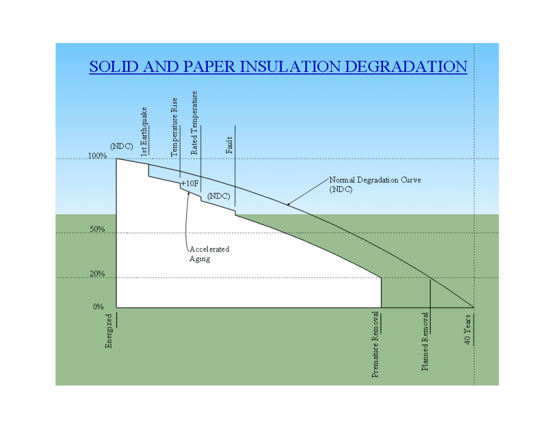
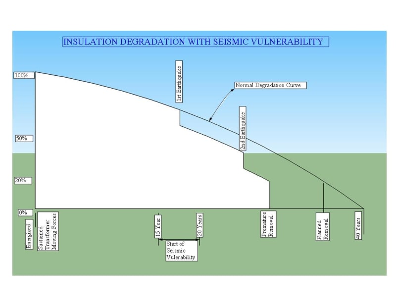
Paper and solid insulation degrade over time until they become weak and brittle and are susceptible to shocks - whether a fault or a seismic event. One issue is the shrinkage of the insulation. When this happens, the result is the loosening of the coil compression forces provided by the clamping bolts. At least two reports and possibly more discuss this. One of these papers also reports the movement of one part of the coils by .59" caused by an seismic event. What may be deduced from this is that transformer normally considered robust, becomes fragile after a number of years. What is this time? Deterioration of insulation is accumulative and cannot be repaired. The apparent result is that transformer life is shortened - possibly by years. Below are two illustrations of solid and paper insulation degradation:
Standard_Degradation_kidlzj.png
Degradation_graphic_for_1-10-20_rrhjgy.jpg
 
1)I was only confessing my inability to pinpoint or even to guess the cause for the specific accident in question. The information is not adequate for me to make any guess. It does not mean others cannot make correct judgement. I only explained probable causes based on my experience of handling similar cases. I was not suggesting anything about the scope of the forum and I have no views on it. I do not know the situation in US; but in many countries legal, insurance and statutory issues are involved with such an accident and we used to be careful while expressing our judgements in public based on inadequate data.

2)If explosion occurs after 57 seconds, it does not mean fault current was flowing till then. Fire spreads gradually and in large units there used to be several explosions as external flames spread deep in to. In large units with oil content as high as 100 kilo-litres, fire used to range for several hours till oil is completely burnt out. Maximum period of current flow in a faulted transformer (interturn short in winding) that I noticed on failure of primary relay (differential relay) was 80 cycles (1.5 seconds) from DR records. There was no tank rupture or fire in that unit. (125 MVA 132 kV)

3)As per my knowledge, there is no chance of any internal air lock up inside an oil filled transformer tank and the same acting as an internal combustion engine cylinder. Transformer oil will have dissolved air to an upper limit of 8-9 %. Maximum dissolved oxygen content in oil is 32000 ppm (3.2%) But this will no way affect fire. Even air with oxygen content equal to or less than 14 % will quench an oil fire!

4)Palletjack, Appreciate your matured and wise advice to young engineers. But I am not giving you any red or some other stars. Probably you may not require or have any value for it! My usual quotes.
(a) To know that one does not know is the first knowledge one should acquire.
(b) To acquire knowledge from the experienced seniors is an art that youngsters should cultivate early in their life.
(c) When we enjoy free lunch, as a minimum courtesy, we should not complain about the dish.

5)I did not ignore anybody. But I refused to respond to inputs as below: I believe there are better ways of expressing one's views or queries. Of course, there are many experts in this forum to answer all queries. Let them oblige. We do not want gold stars or mad respect or any certificates. But minimum courtesy is expected and will be demanded. I am not expecting everybody to accept my views. But it is not my job to submit calculations in triplicate to non-believers for their education. Quote
-@PRC: I'm confused why you say this or why you have a star?
-So, you are trying to tell me a transformer will not catch fire if short circuited indefinitely? Unquote
This is not an isolated case. In another thread, under similar situations, a senior member of this forum exclaimed "bullying? " and left the discussions altogether.

6)cuky 2000, you have raised questions and given answers too. So, nothing more to add to your copy. Oldrunner, suggest to start a new thread as it seems a new topic.

7)Next month,I will be calling it a day from my continuous 54 years of 9-5 working life with transformers. (may be from this forum too) No offence or malice meant to anybody. This is my last post under this thread.
 
prc:
Actually I think my thread is very important and is appropriate for this topic. Degradated insulation is discussed in many papers and in the FIST and NIST recommendations. What I haven't seen is the importance of considering earthquake forces along with the electrical forces as well as considering time and heat. I have a few years of engineering also, 60 years from college and 50 years from obtaining my SE. Also have reviewed numerous transformers for conformance to the IEEE 693 code. Almost everything that I mentioned can be referenced to documents readily availagle from the net. The insulation degradation and loss of compression in the coil assembly is from a technical paper from a insulation manufacturer. (3 authors). The coils losing compression and movement from TEPCO. Do you have a solution for avoiding seismic forces to the coils and core? Do you have a comment on risk of an explosion of a transformer that is 25 years old and located in high earthquake country?


PRC said:
4)Palletjack, Appreciate your matured and wise advice to young engineers. But I am not giving you any red or some other stars. Probably you may not require or have any value for it! My usual quotes.

There is nothing matured or wise about disparaging others much less enabling hostile behavior. I myself don't defend nor do I condone such.

(a) To know that one does not know is the first knowledge one should acquire.

Which is why I'm asking you how many BTUs of heat were released into the oil in those 57 seconds. That is a legit question, not an assertion. Because I genuinely do not know.


(b) To acquire knowledge from the experienced seniors is an art that youngsters should cultivate early in their life.

If you look at my post history, I've always listened to those who know more than I do. And those who are still learning. I listen, period.


(c) When we enjoy free lunch, as a minimum courtesy, we should not complain about the dish.

Asking questions is not complaining. I'm sorry you feel that way about education, and perhaps individual perception is the root of the issue at hand.

If explosion occurs after 57 seconds, it does not mean fault current was flowing till then.

We see arcing in those 56 seconds, the transformer was under profound over load. I'm not saying anything had already faulted internally.


7)Next month,I will be calling it a day from my continuous 54 years of 9-5 working life with transformers. (may be from this forum too) No offence or malice meant to anybody. This is my last post under this thread.

Which is why I'm directing these questions at you. 54 years of transformer manufacturing experience will yield an answer better than anyone else can here- bar none.
 
@Oldrunner: Your topic is very appropriate for this thread. Share what you need to, ask what questions you need to. I'm learning lots and you are immensely adding to the discussion.
 
To address this as it seems like the crux of the matter:

PRC said:
5)I did not ignore anybody. But I refused to respond to inputs as below: I believe there are better ways of expressing one's views or queries. Of course, there are many experts in this forum to answer all queries. Let them oblige. We do not want gold stars or mad respect or any certificates. But minimum courtesy is expected and will be demanded. I am not expecting everybody to accept my views. But it is not my job to submit calculations in triplicate to non-believers for their education.

I do not see anything wrong in asking for equations. There is no offense committed in such as mathematics is the language of the universe, the language of God. So a mathematical explanation will help me understand this scenario best.

MBROOKE said:
Quote
-@PRC: I'm confused why you say this or why you have a star?

Respectfully I feel this to be incorrect:

PRC said:
If fuses are used for protection, two types of fuses are put in parallel on primary side- expulsion fuse ( to protect from over loads and secondary side faults) and current limiting fuses

In the United States medium sized power transformers are not equipped with current limiting fuses in series with the primary expulsion fuse when fuse protection is employed. For example, SMD-2B power fuses:


PRC said:
This will prevent a tank rupture and consequent transformer fire.

SMD-2B fuses will not prevent tank rupture or fire as they do not have any current limiting properties. Further, transformer fire and explosion is far more likely to take place with fuses as they typically operate slower, do not detect turn-to-turn faults nor trip on oil leaking out of the transformer. Among other issues.

Power fuses are by far the worst way to make sure catastrophic failure takes place outside of no protection at all.


MBROOKE said:
-So, you are trying to tell me a transformer will not catch fire if short circuited indefinitely? Unquote

Was in response to this:

PRC said:
Transformer fire normally is not due to any sustained fault on secondary side.

But here we do see a sustained secondary fault going on for at least 57 seconds, more in reality.

An arcing fault will have impedance (this has been studied extensively by UL to the point it put AFCIs into the NEC and now AFDDs in the IEC) limiting current below the short circuit values listed in standards.

IMO, this will give more time for heat to migrate into the oil before an internal fault develops. The paper is also heated more slowly.

The thermodynamics is different IMHO hence my curiosity... Thats all I'm getting at.


PRC said:
This is not an isolated case. In another thread, under similar situations, a senior member of this forum exclaimed "bullying? " and left the discussions altogether.

Do you have a link? If I did say anything that upset others or am inadvertently bullying I would like to know about it and make an effort to change my behavior.
 
PRC:
I meant to compliment you on your paper "Prevention of Accidents in Distribution and Power Transformers" the other day. I have had some of your type of experiences also. Early on, my company was involved in moving a transformer from the RR siding in a small town in northern California. Basically shut the town down; Transformer off-loading onto a new trailer that I had designed just a few weeks earlier. Never tested. I was involved in reviewing one bridge made up three types of bridges; steel truss, concrete T-Beam with curved soffits, and a flat slab section. The day before the move I told the families of some workers living under the bridge to not be there when the load went across the bridge. In my review of the two lane bridge, I assumed that the trailer behind the two pullers would stay in the center of the bridge. Also, as the engineer of record, I was to walk behind the trailer during the move. So what did I learn? Even though the pullers stayed in the center of the bridge, the long trailer (overall length which was about 235 feet), wandered back in forth while going across the bridge. The original hauling unit was to be a Schuerle multiwheel unit, each wheel steering and independent suspension with the hydraulics power by a VW engine.
Should end this as off topic, but I wonder if your were involved in the video made in a ABB plant in India which has a section of a core-coil assembly being moved very carefully from one part of the plant to another. And to imagine that that carefully constructed assembly could someday be subjected to violent shaking!
 
prc
I wish you the best in your retirement.
Please forgive me if I have upset you or seemed to disrespect you.
I have the highest regard for you.
I value your advice and years of experience and education.
I agree with you that we won't know positively what the failure sequence was until we see an official report.
We are speculating, and your input, based on your knowledge and experience, is heavily weighted in our estimation.
As we speculate, we receive new insights from experts such as yourself.
We are not trying to come up with a cause of the event that will stand up in court or will satisfy an insurance company, we are trying to learn more about the various factors involved in transformer failures and tank ruptures.
We thank you most sincerely for your input and beg you to rejoin the speculation.

A couple of points of clarification: (For others, not for you, prc. I know that you know this already.)
Short circuit withstand;
1) As per IEC 60076-5, transformers are designed to withstand thermally 2 sec of over currents. Copper temperature from the heating at the end of 2 sec shall be less than 250 C.
That would imply that a transformer will survive a 2 second short circuit.
Thus the time to failure under short circuit conditions will be more than 2 seconds.
Time constant:
The definition of time constant that I have learned is:
When a value is changing (heating, the current charging a capacitor, current building in an induction coil, etc.) in response to a step change, the time constant is the time to reach about 63% of the terminal or steady state value from the value at the time that the step change occurred.
The value is generally accepted to have reached steady state after 5 time constants.
Final or stable temperature is reached when the heat input equals the heat rejection.
BUT, that's not the only factor.
With a bolted fault the windings would theoretically reach a stable temperature in 30 to 50 minutes.
There are two caveats to apply.
1. An external arcing fault will be less current than a bolted fault and the final or terminal temperature will be lower.
2. The winding will often fail before the final temperature is reached.
Example of time constants.
Initial temperature = 0 degrees and after a step change in heat input the temperature stabilizes at 100 degrees.
The time constant is the time to reach about 63 degrees or 63% of the temperature change.. After 5 time constants the temperature will stabilize at 100 degrees.
After the second time constant the temperature will have reached: 63 deg. + ((100-63) x .63) = 86.31 deg.
The third time constant will see: 86.31 deg + ((100 - 86.31) x .63) = 94.93 deg.

If you want an exact figure to replace 63% use 1 minus the reciprocal of the mathematical constant e, where e is an irrational and transcendental number approximately equal to 2.718281828459
1 - (1 / 2.718281828459) = 1 - 0.3678794411714484‬) = 0.6321205588285516‬ = 63%

Has the Leidenfrost effect ever been considered or investigated in regards to transformers and the heating of the oil, and the heating of the copper when it is above the Leidenfrost point and less heat is conducted away by the oil?
eg: Copper heating more rapidly as less heat is transferred to the oil.
WIKI said:
The Leidenfrost effect is a physical phenomenon in which a liquid, close to a surface that is significantly hotter than the liquid's boiling point, produces an insulating vapor layer that keeps the liquid from boiling rapidly. Because of this 'repulsive force', a droplet hovers over the surface rather than making physical contact with the hot surface.

This is most commonly seen when cooking, when a few drops of water are sprinkled in a hot pan. If the pan's temperature is at or above the Leidenfrost point, which is approximately 193 °C (379 °F) for water, the water skitters across the pan and takes longer to evaporate than it would take if the water droplets had been sprinkled into a cooler pan.

The effect is named after the German doctor Johann Gottlob Leidenfrost, who described it in A Tract About Some Qualities of Common Water in 1751.


Bill
--------------------
"Why not the best?"
Jimmy Carter
 
If the windings in a transformer reach the Leidenfrost effect temperature, the heat will be removed from the windings at a slower rate.
This may affect the time constant.

Bill
--------------------
"Why not the best?"
Jimmy Carter
 
@Waross: Thank you, these are the answers (and numbers) I'm looking for.

FWIW I'm still trying to nail down the RMS of that arc fault, which is a fascinating subject all on its own.
 
Also wondering (hunting for) the watts loss of the primary and secondary windings for a given short circuit current. As well as the heat given off by the iron core from eddy currents, hysteresis loss, ect during this state.

Heating of the windings themselves increases DC resistance further limiting current.


On a side note, I was once running an experiment where I discovered that it takes a lot of space heaters to burn down a home. Not that I actually did or was trying to start a fire, but curious about overloads and electrical fires. As you switch in each heater the voltage drop becomes so significant on a typical home run that the current draw curve becomes very none linear with each heater turned on. The TV shutting off and the dimming lights become so pronounced this alone is a deterrent or indicator. The 14-2 got hot sure, but not enough to melt its insulation (not 90*C let alone over).

The real hazard comes from the stress back stabbed connections have to endure from such chronic over loading (loosening eventually leading to joule heating) or a short circuit with the OCPD failed or bypass (penny behind the fuse).

I have to say it went against conventional wisdom- but then again most homes have survived with 30 amp fuses and a single circuit per floor.

Not that I advocate for violating code, but electrical fires from failed insulation due to overloading (or overloading in general) is near the bottom of the list. The impedance of the circuit is rather good at protecting life and property.
 
Your mission, should you choose to accept it, is to do some Google searches on the impedance (resistance) of arcs of different lengths and report back to us.
What do you do with the arc resistance when you find it?

Work backwards from the transformer % impedance to find the Ohms impedance.
Then use the X:R ratio to resolve that into resistive and inductive components.
Add the arc resistance to the transformer resistance and calculate the impedance of the circuit comprised of the transformer impedance and the arc impedance.
Now you can get an idea of the current and of the Watts loss in the transformer with a three phase arcing fault on the secondary.
Add a factor for copper heating and a factor for primary voltage drop.

Bill
--------------------
"Why not the best?"
Jimmy Carter
 
@prc, Please don't retire from the forum Sir!
I learnt a lot from you and Look forward to your messages when I ever I access the forum.
I am sure you too enjoyed sharing your knowledge with others and request please do continue.
Thanks.
Wish you, in advance, happy retired life (from company service).
 
1) Normally I never break my vow. The vow- this is my last post under this thread - has to be broken as Bill is very special to me and I cannot keep silent when he posts serious matter based on his strong footing on fundamentals and vast and varied experience.

2)Let me assure, I am not upset with anything that waross has explained. Last 20 years I learnt a lot from his prolific postings. Let me make little more explanation for my understanding of this problem, no way questioning judgement of waross.

(a) I believe what you interpret as arc flash for 57 seconds is actually flames from oil fire. You can get actual period of current flow only from DR data. You may say that it is not full bolted current. If we accept it, then it can happen if a neutral grounding reactor or resistor is put on secondary neutral. Then LG fault current will be few tens,but such size of arc flash cannot come out from such magnitude of current. So my stand is there was no fault current flow for 57 seconds.

(b) Some history- I had mentioned that transformers are designed for thermally withstanding SC current flow for 2 seconds. But failures under SC conditions are always during the first 1-3 cycles. This we have noted during SC test at Power Labs and also from DR records of transformers failed at site under SC conditions. There was a stipulation in utility transformer specifications 50 years back- Transformer shall withstand dead 3 phase short circuit on secondary terminals with full energy feed from primary without any grid voltage drop. Manufacturers used to give readily OK, knowing well no way for user to check it- no standard calculation method and non-availability of power lab of adequate capacity for SC test. Later IEC put 5 second withstand capability. From actual failure mode at site, IEC later changed this to 2 seconds, current norm.

c) You have lucidly explained thermal time constant. Winding thermal time constant of modern transformers is 6-9 minutes. Loading guides have taken care of the points you have explained ie it changes during overloading. I am hearing first time Leidenfrost effect. Thank you. But a few years back ABB Finland engineers had discovered the effect of this phenomenon -an overshoot in winding hot spot during overloading that will come down after some minutes. Any way all these + calculations that I had made foe SC conditions make it clear that oil will not overheat or boil during SC conditions.

d) All these latest understanding on heating and cooling of transformers is given in CIGRE Brochure No.659-2016 -Transformer Thermal Modelling of Transformers.

3) oldrunner- In case you are interested in Transportation of Transformers - Please have a look at IEEE standard C57.150-2012 Transformer Transportation + CIGRE Brochure no.673-2016 Guide on Transformer Transportation.

4) Raghu, thank you for your compliments! We are meeting quite often in linked in groups. I am also planning two columns in a magazine - on Transformer standards and Transformer Books. So when I plan to slow down, my presence here also will be low. Not retiring fully.
 
PRC said:
(a) I believe what you interpret as arc flash for 57 seconds is actually flames from oil fire.

In all due respect I hear 120Hz humming (listen to the audio turned up):


And here, noise consistent of external arcing:


In addition to the damaged busbar Cucky2000 posted hinting at potential arc damage.

Again, this is in no way meant to discredit, insult or troll you. I believe this simply to be a difference of observable perception, and in such a case can we respectfully agree to disagree? I'm ok with agreeing to disagree. [peace]

I could be wrong and thus in the end I am willing to accept that time come.

With that said I hope you post more here, I enjoy your time.
 
@Waross- I'm searching- but I'm debating on whose equations to use based on how they were derived which is murky. The thing about arcing is not just electricity going through nitrogen, but the fact the arc picks up and drops out at different points in the sine wave.

UL's testing found as much as quarter and half cycling for parallel arcing faults, but this is obviously for lower voltages.

I'd be lying if I could guess the distances involved in the Burbank Substation- anyone know of the bus duct used in this station?

But thank you- in no disagreement.
 
Thank you for your comments prc.
I am basing my guess on the intense white light and brown smoke emitted for an unknown time period of greater than one minute.
This abruptly changes to red flames and quantities of black smoke.

Time to damage is based on a bolted fault. The time for that damage to cause an internal failure may be expected to be much longer.
Line voltage drops and the lesser current from an arcing fault compared to a bolted fault will not change the time constant.
The lesser current will, however, lessen the final temperature significantly.
The result of that will be a longer time to reach a given temperature and a longer time to first damage and a longer time to failure.

Here are some more informed guesses;
Bus bar spacing for 12.2kV305 mm (15 kV class, CEC table 30)
Arc voltage 1.2 Volts per mm = 366 Volts (researchgate.net)
Unknowns that someone else can guess:
Size of the transformer.
% impedance of the transformer.
X:R ratio of the transformer.
The impedance of the conductors between the transformer terminals and the fault location.

There are a couple of conclusions that may be drawn from your information, prc.
Not exact but interesting.
Given:
The winding will approach 250C within 2 seconds starting from the specified test temperature.
The time constant of the winding is from 6 to 10 minutes.

Taking 250 degrees and 2 seconds, and playing with exponents it is possible to calculate the corresponding temperature at 6 minutes.
As the temperature at 2 seconds may be less than 250C, the calculated temperature may be less than the actual temperature.

There was a time when I enjoyed playing with exponents.
Not any more.
Short term memory loss and slower thinking are starting to rob me of my confidence.
(I really hope that it is age and that I am not sliding down the Dunning-Kruger curve.)
I'll leave the calculations to younger minds.
The floor is open.


Bill
--------------------
"Why not the best?"
Jimmy Carter
 
waross got me thinking... and the quarantine boredom gave me the opportunity :p

The thing is that calculating the temperature increase for the first seconds of a fault it's very easy, the standard formula only needs the conductor material and the fault current density. But this its an adiabatic approximation, good for 10 seconds or less, if I recall correctly.

When you move further in time the thing complicates as you can no longer ignore the heat transfer to the medium, and you must fall into the realm of differential equations (or at least exponential eq).

That sounds too complicated for me, I'll also leave it for younger (although I'm not that old) or sharper minds.

But, if you concede me that you can consider a sustained fault current as a "severe overload" current (just for an approximated thermal evaluation), I can do some math... taking the exponential equations for temperature increase at over-load given by IEC 60076-7 standard (something similar could be done with ANSI/IEEE, but I'm a IEC guy).

To be clear: I don't claim that this is the correct way to calculate temperatures in fault conditions, I'm sure it isn't, for all the reasons already explained in this thread and because this method was developed for other reasons (transformer ageing assessment).

But it could give us an idea of how fast the temperatures inside the transformer can rise and may illustrate some points given in previous posts.

Attached you can find an excel spreadsheet with the IEC formulas and some typical values for a medium power ONAF transformer. I've assumed a fault current of 11 times the rated one (seemed a logical value) and that the transformer was at full power just before the load step.

For short periods of time this calculation will tend to underestimate the temp rise (I don't even know if you can use it for time shorter than 1 min).
And for longer periods of time it would overestimate it, as it considers a constant "fault current".

Again, it is only meant to give an overall idea of the thermal behavior of an overload transformer.

Feel free to play around with it. And please check for errors (I hope the sheet works in other languages).
 
 https://files.engineering.com/getfile.aspx?folder=7e43de71-feb1-40f6-9f13-a328ced02317&file=IEC_load_guide.xlsx
waross, let me supplement to the extent of my under standing:
waross said:
[Time to damage is based on a bolted fault. The time for that damage to cause an internal failure may be expected to be much longer.]
As I mentioned earlier, the failure normally used to be during first 1-3 cycles due to dynamic forces from asymmetry peak. If it continues and comes down to RMS bolted fault current value, then after 2 seconds, the copper temperature should be less than 250C. Problem is after 250C, the interturn kraft paper ( earlier class A , today 105C) will start charring. This paper thickness between two strips is only 0.3-1.2 mm. In no time it will be burnt out and turn in to a interturn or inter disc short circuit, dropping secondary load current to zero, leading in to failure modes we discussed earlier. Heating up will be faster as copper resistivity will go up when temperature increases.

When copper temperature reaches around, 140C , gas bubbles will be coming out of interturn paper insulation -this is partly moisture turns in to steam + oil breakdown. These bubbles (permittivity =1) when move around electric field, breaks down leading to creep + electrode to electrode failure. So before reaching higher temperatures, transformer will fail through dielectric break down.

Another major issue is thermal run down due to stray loss and leakage flux. When current increases by 10 times, leakage flux from windings also increase by 10 times. This will heat up the metal parts and tank if current is maintained for a few seconds. This is so intensive as to cause the metal to turn to red hot.

Part of the above huge leakage flux will enter in to yoke and supersaturate it; increasing excitation current and core losses.

I have never seen any body modelling for such long duration SC current heating; probably it is understood that such a situation is not feasible as breakdown should occur well before. Loading guides consider permissible short time emergency loading(for less than 30 minutes) for transformers as 2 Times for distribution transformers, 1.8 times for medium transformers and 1.5 times for large units (100 MVA and above).Even there code caution about huge loss of insulation life(17 times more even at 140C; allowable hot spot temperatures under that condition 160C)

As mentioned earlier postings, this 2 sec copper temperature is assuming the entire heat is stored in copper, due to the effects, you had explained from fundamentals. Suppose the winding is subjected to a 120% over current (over rated current) from full load. at 20C ambient, the copper temp at start will be 98C. Let us say with 120 % continuous current, the stabilized final copper temperature is 140C ( considering extra I2R losses & extra heat dissipation in to oil).Temperature rise will be faster initially but final stages will be very slow. The winding time constant of 6 minutes is the time taken for copper to reach 124C [(140-98)0.63 =98]
 
Status
Not open for further replies.

Part and Inventory Search

Sponsor