Continue to Site

Eng-Tips is the largest engineering community on the Internet

Intelligent Work Forums for Engineering Professionals

  • Congratulations KootK on being selected by the Eng-Tips community for having the most helpful posts in the forums last week. Way to Go!

Linear motion - how to decrease (shear) pull force 1

Status
Not open for further replies.

free_flyer

Aerospace
Aug 16, 2020
7
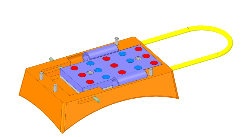
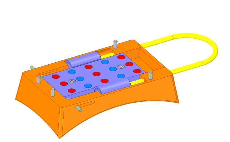
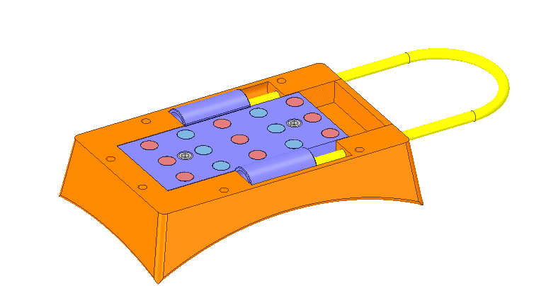
My design has a linear, sliding 'cassette' [purple] which slides by pulling on the teflon cable [yellow]
1_eh3r9i.png


In the cassette are magnets (x15) which attract to a mating part (not shown) with the same number of magnets but with reversed poles.

When the cassette is in the closed position, the magnets attract and hold the mating part.

When the cassette is in the open position, the magnets repel and eject the mating part.

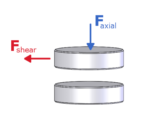
In terms of magnetics, when the cassette is in the closed position the force required to slide the cassette open is known as the 'shear' force, whereas the force between the mating parts is known as the 'axial' force..
4_haiupm.png


I have a working prototype, but I am trying to reduce the shear force required to slide the cassette to the open position (i.e. to eject the mating part)

Currently (when the cassette is in the closed position) the shear force to slide open the cassette is around 6 to 7 kg and the axial force between the mating parts is about 10kg.

Ideally I want the axial force to be as large as possible (when the cassette is in the closed position) yet the shear force to be as small as possible.

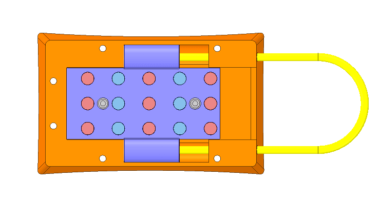
Below is a top view showing the cassette in the closed position...
2_nmiidn.png


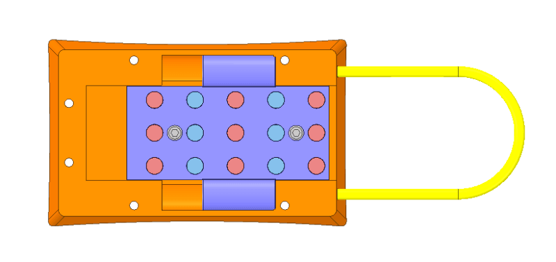
Below is a top view showing the cassette in the open position...
3_gwk9oc.png


The distance the cassette moves is around 12mm (i.e. between the open and closed position).

I've been trying to think of a way to decrease the shear force to slide the cassette open, without having a detrimental effect on the axial force (such as creating an air gap between the mating magnets).

Originally the cassette ran on linear bearings and rails, but these made little or no difference to the shear force so I removed them.

I then looked into something like a rack and pinion (does this even give a gearing advantage?)and other kinds of gear and cam mechanisms, but I've made no progress.

How can I reduce the shear force to slide the cassette open and preferably without increasing the size of the design too much ?
 
Replies continue below

Recommended for you

The proposed system seems incredibly complicated to accomplish this task.
 
Maybe don't have a protrusion that can allow a cord to catch on. I've seen the same stupidity on Tucker Gott's channel from bad mounting of cameras.
 
Hi itsmoked

Well similar to trying to push a flexible cord against a spring into just bends out of the way, you can only put a flexible cord in tension eg when pulling the carriage to the open position, so if you replace the spring with opposite pole magnets to make opening easier, it then makes insertion harder because the magnets positioned to create shear force will oppose the cord insertion.

“Do not worry about your problems with mathematics, I assure you mine are far greater.” Albert Einstein
 
In terms of resetting the cassette to the closed position, a temporary tool could be used that fits into the cassette to help pull it back...

1_pmfc8w.png


2_mcrlic.png


To answer some of the questions:

@itsmoked: "Would seem like an FAA kind of problem though letting solid objects fall (bomb) to the ground." - this is why we jump at designated, approved airfields (dropzones)

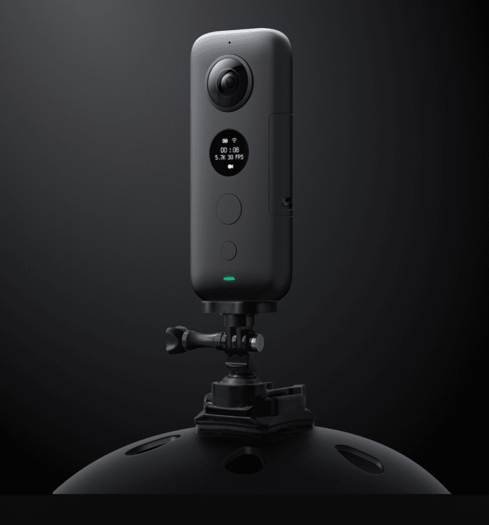
@3DDave: "Maybe don't have a protrusion that can allow a cord to catch on" - this would be the ideal option but doesn't exist. In fact the 360 degree cameras (like the Insta 360) are even more obtrusive yet becoming more common in the sport...

3_li9mkg.png
 
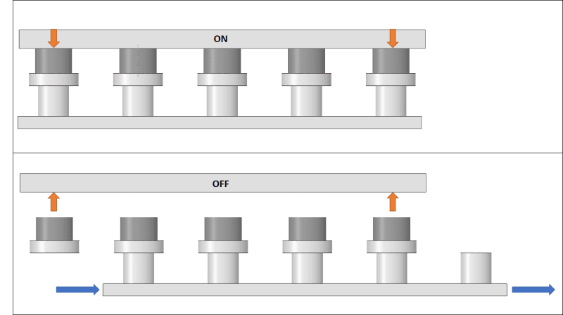
You may benefit from looking at how a magnetic switch works. The example below is a rotational one, but linear versions are used in metal working. You can use an eject spring or two instead of the magnetic repulsion. There are a wide selection of spring variations. The advantage is the base of the camera mount is just a steel plate, all the magnets are in the helmet mount - more than that, it won't be a constant struggle to clean small bits of steel that will eventually find their way to an open magnetic field.

is the part of the video that explains the theory; back up to the beginning to see a short demo and how it's built. In his baltic-birch version it appears capable of holding far more than you need, so scale accordingly. As I say, linear versions are used in machine shops. However, like all magnetic applications, even small gaps will cause significant drops in magnetic force, so contamination awareness needs to be high.

Here's an example of why being able to turn the magnet off can be handy. It's a different style of switched magnetic field, but it's a great comparison to what an always-on magnet can collect.
I expect if you key the camera plate to the top of the switch into a recess, then instead of a loop that is snaggable, just twist the camera to release if the round version is used; nothing is available to get snagged. Depending on the number of poles one might reduce the motion as much as one likes. 4 = 90, 6 = 60, 8=45 degrees.

If it's linear one can set the step size as small as one likes depending on how thin the magnets and plates are - a few millimeters from full force to release if desired. Use a flip lever with an eccentric to move the switch and get considerable leverage.
 
Thanks 3DDave, its ironic you talk about designing a magnetic switch as this was the original design.

It was also based on the design from a youtube videos shown below...

[URL unfurl="true"]https://www.youtube.com/watch?v=dSdL7FlGlVc[/url]

[URL unfurl="true"]https://www.youtube.com/watch?v=KXBQA_OiOfk[/url]

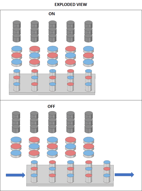
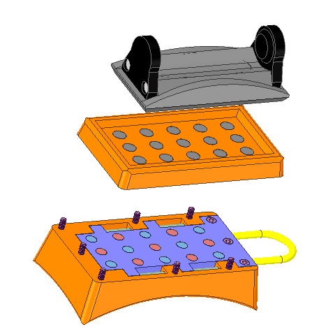
My earlier design which used this principle is shown below...

1_dmhsnk.png


2_ejsjzv.png


3_dv7n4w.png


4_p5clbh.png


5_izzcvg.png


In the youtube video, the magnetic switch used tapered steel poles but these proved to be difficult to source without spending a fortune to have them custom made. Even trying to source straight 6mm diameter x 4mm height steel poles was difficult/expensive. The only solution I found was to purchase 6mm diameter x 4mm height neodymium magnets and then heat them up to de-magnetise them ! In the end I did not prototype this design, but I did contact the person who uploaded the videos to ask for advice. When I explained the design he said...

"The tapered pole pieces are tapered to focus flux there’s no real force on them when the things off, I’m sure you’ll be fine with straight ones for the prototype. I think the issues you’re going to have with your design as is, are not magnetic but mechanical and physiological (from bitter experience).

As the magnets move from the on to the off position the attractive force becomes repulsive and the top and bottom portion of the switch are then trying to blow themselves apart. Whatever the 3D printing material is will need to withstand these forces to prevent the thing fracturing.

In addition to the force required to bring the 12 magnets into opposition, your thumb and forefinger are also going to have to overcome any friction caused by any sliding faces being forced together. When you’re switching the rotary one you have a mechanical advantage and a very small bearing face; not so on the linear one. My linear prototype didn’t have as many magnets as your design but was still a bit hard to switch.

But you're in luck here if you want the camera to be jettisoned.

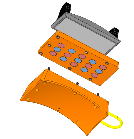
If you don't screw the two orange surround parts together (the magnets will do that) and just use dowels instead, If you do you pull that chord, sections 1 + 2 will be pushed apart by the repulsion of the magnets and hopefully off your head.

The top of the surround and the camera mount (1) will remain in one piece but so will you and I suppose that's the result your ultimately after.

One word of warning there's a chance the top and bottom half could come off the dowels and move sideways sticking to the magnets next to them but you could mould in some features into the mating faces of the surrounds to stop that ever happening."


So from this point on, I changed the magnetic switch design to the design where the mount is ejected. It also meant less parts (and no need for hard to source straight/tapered steel pins) which also meant that the height of the design was reduced.
 
If you must use magnets, why not position them so they're permanently set to repel the camera, then latch it into position with something like a one-shot Capewell?

A.
 
In the YouTube video I sent you they used cylindrical magnets and cylindrical rods, not difficult to source. It looks like Kinsey was worried a straight rod would pull out. Instead of rods, hex-nuts would also work for your configuration, though I am not sure they are needed for the vertical stacking of magnets, except to avoid damage to the magnet surfaces. It's also unclear why two sizes of magnet are used.

Focusing flux is normally used in conjunction with Hall effect sensors to increase magnetic gradient and improve the positioning precision. This is not a factor for this application.

As I said, the point of magnetic cancellation is so the device does not become a crap trap.

You know that the shear force is from the same magnetic attraction that is the source of the axial force, right? That this component is independent of friction? From it is 40% to 70% of the axial force, so very much in line with your observations. Notice that the spring suggestion works by pushing the magnets off center and reducing axial force.
 
Have you considered a magnetic field shutter/shield that can be moved axially between the opposed magnets?

Walt
 
So, if you are using magnets, then use them the whole way.

Ditch the sliding concept.
When the magnets are disengaged, the part falls away, no sliding.

The cable is replaced with a "T" handle.
Grab T handle
Twist it... thus disengaging the magnets with a cam.

Magnets gone, T handle separates with the part in your hand.

Grab, twist, done.
 
Status
Not open for further replies.

Part and Inventory Search

Sponsor