-
1
- #1
JustUseSteel
Structural
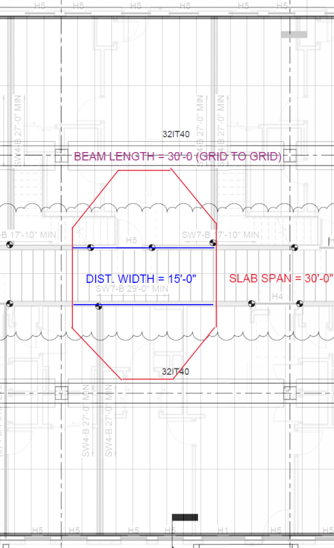
Hello, first time posting but look here often. I'm getting into some debates in the office on handling LLR in precast structures. There's a few different concerns here so I think I'll start with the most basic: See the attached image of the precast floor plan, and an overlay of a joist framing layout from above. The center bay of precast slabs has two load bearing walls running perpendicular to the span supporting 5 levels of units above, plus a roof. Ignore any additional complexities like the stairs or anything else not mentioned.

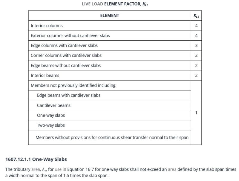
Is it the code intention to allow a different live load reduction factor for slabs, beams, and columns? My stance is that if you want to get as much LLR as possible, you should calculate LLR per member. Generally for a slab you might see a reduction of 40%, a beam 50%, and a column 60%. In these debates I've heard these alternates:
1. Whatever you use for the slab should also be used for the beams and columns. That doesnt make any sense to me; the beam is less likely to have its full influence area fully loaded, so it would be allowed a greater amount of live load reduction.
2. The floor itself has a live load reduction, and not individual members -- so beams and slabs would have the same live load reduction, but the columns are allowed more. Again that doesn't make sense to me because LLR is statistical and a "floor" isnt a discrete thing you can analyze.
My second question is getting more specific on LLR and one-way slabs. For a bit of background on precast hollowcore, PCI recommends a "distribution width" of 0.5*Span at midspan, with the shape shown in the image earlier. The ends are around 4 feet wide, depending on the situation. This is a simplification of moment distribution and the load itself is not truly being distributed. For calculating your tributary area here, the method I've seen is to take these areas and add them together:
1. Area of slab itself 0.5*ClearSpan^2)
 0.5*ClearSpan)*(NumFloors)*(JoistSpan/2)
For the most part, this makes sense to me. My concern with this comes as that bearing wall gets closer to the end of the slabs (i.e. nearer to the precast beams). At this point, the slab is becoming shear controlled, and I don't see how taking 0.5*ClearSpan as your slab width for LLR is valid. Testing shows that a load applied at the end of a hollowcore plank distributes "instantaneously" about 4 feet. So, in my view, the tributary area for SHEAR can be different than that used for flexure. Let's say there is only one blue bearing wall, and its 1 foot from the beams (and running parallel as shown). That distribution width for shear is then approx 4 feet wide, and my opinion, the tributary area is now:
1. Area of slab itself: (4ft)*ClearSpan = 120ft^2
2. Area of all 5 supported floors above: 4ft*(NumFloors)*(JoistSpan/2) = 350ft^2.
My reasoning is that if only this 4 foot chunk of bearing wall was fully loaded, this unit of slab would see its maximum shear. So, how can I rationalize using a larger LLR? Hypothetically the wood framing/bearing walls can spread the loads out, too... which is the best rationale I can come up with. But in my discussions it seems no one agrees with the exact location of the loads on the slabs as mattering for calculating LLR. Always use 0.5*ClearSpan for a transverse load. (Point loads of course have their own discrete area)
Would greatly appreciate input! Hopefully I've made some degree of sense here.

Is it the code intention to allow a different live load reduction factor for slabs, beams, and columns? My stance is that if you want to get as much LLR as possible, you should calculate LLR per member. Generally for a slab you might see a reduction of 40%, a beam 50%, and a column 60%. In these debates I've heard these alternates:
1. Whatever you use for the slab should also be used for the beams and columns. That doesnt make any sense to me; the beam is less likely to have its full influence area fully loaded, so it would be allowed a greater amount of live load reduction.
2. The floor itself has a live load reduction, and not individual members -- so beams and slabs would have the same live load reduction, but the columns are allowed more. Again that doesn't make sense to me because LLR is statistical and a "floor" isnt a discrete thing you can analyze.
My second question is getting more specific on LLR and one-way slabs. For a bit of background on precast hollowcore, PCI recommends a "distribution width" of 0.5*Span at midspan, with the shape shown in the image earlier. The ends are around 4 feet wide, depending on the situation. This is a simplification of moment distribution and the load itself is not truly being distributed. For calculating your tributary area here, the method I've seen is to take these areas and add them together:
1. Area of slab itself
so this is just taking the area of the distribution width as a rectangle; slightly unconservative but inconsequential. (0.5*30*30 = 450ft^2)
2. Area of all 5 supported floors aboveand this is taking the area of joists supported by all bearing walls on the distribution width. Typically that might be a corridor width of 5 feet, and a span to the exterior wall of 30 feet; leaving you with a supported area of (0.5*30feet)*(5)*(30ft+5ft)/2 = 1312ft^2
(per wall)For the most part, this makes sense to me. My concern with this comes as that bearing wall gets closer to the end of the slabs (i.e. nearer to the precast beams). At this point, the slab is becoming shear controlled, and I don't see how taking 0.5*ClearSpan as your slab width for LLR is valid. Testing shows that a load applied at the end of a hollowcore plank distributes "instantaneously" about 4 feet. So, in my view, the tributary area for SHEAR can be different than that used for flexure. Let's say there is only one blue bearing wall, and its 1 foot from the beams (and running parallel as shown). That distribution width for shear is then approx 4 feet wide, and my opinion, the tributary area is now:
1. Area of slab itself: (4ft)*ClearSpan = 120ft^2
2. Area of all 5 supported floors above: 4ft*(NumFloors)*(JoistSpan/2) = 350ft^2.
My reasoning is that if only this 4 foot chunk of bearing wall was fully loaded, this unit of slab would see its maximum shear. So, how can I rationalize using a larger LLR? Hypothetically the wood framing/bearing walls can spread the loads out, too... which is the best rationale I can come up with. But in my discussions it seems no one agrees with the exact location of the loads on the slabs as mattering for calculating LLR. Always use 0.5*ClearSpan for a transverse load. (Point loads of course have their own discrete area)
Would greatly appreciate input! Hopefully I've made some degree of sense here.


