Continue to Site

Eng-Tips is the largest engineering community on the Internet

Intelligent Work Forums for Engineering Professionals

  • Congratulations pierreick on being selected by the Eng-Tips community for having the most helpful posts in the forums last week. Way to Go!

Load calculation on lifting inserts

Status
Not open for further replies.

dstruct99

Structural
Jul 7, 2022
10
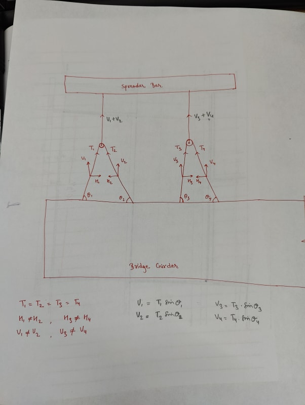
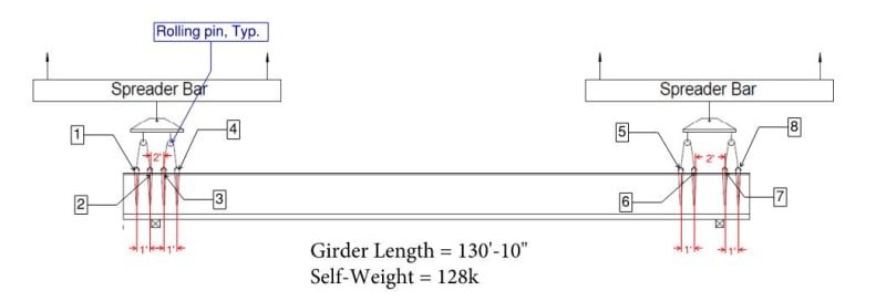
How would you approach calculating loads on each of the lifting inserts (4 on each side, Total 8)? The inserts are mirrored to each side. Please refer to the attached image or PDF below.

Two schools of thought:
1. The load is distributed on each of the lifting inserts based on the tributary weight of the girder.
2. The loads are distributed equally on each of the 8 inserts because of the equal tension force in the cable, and the spreader bar with the rolling pill will help distribute the load equally.

I appreciate your time and thoughts on this.

Lifting_inserts_image_wfqeok.jpg
 
Replies continue below

Recommended for you

With rolling blocks in this configuration, the loads in each line are equal. The angles of the lines may not be equal, and therefore you might have more vertical reaction at one insert than another. Depending on the stiffness of your girder (stiffer is better) and lengths of rigging (longer is better), this effect is often but not always very small.

Note that riggers are generally not a fan of two tiers of rolling blocks, as they're difficult to handle in the field.It happens, but expect to get some complaints.
 
Thank you Lomarandil for your input.
Please see the sketch below to see if I'm understanding you correctly. It was interesting you said that the girder needs to be stiff. Is that because the stiffness of the girder is required to transfer the girder's weight from the lifting inserts 3 or 4 to the far end i.e. 1 or 2?
Let's say the girder was not stiff enough, would you agree the majority of the load (half of the weight of the girder in this case) would just go to connection points 3 and 4?

IMG20240429153905_j64hua.jpg
 
Yes. You can imagine that if the girder is not stiff, it would deflect substantially at midspan. In this case, the girder would primarily load points 3 and 4, points 1 and 2 would deflect up and their rigging would go slack. This happens to a certain degree in all practical cases, but if the girder is stiff enough, the deflection upwards is small and the vertical reactions among all points may be nearly equal.

Now, looking at the sketch, I don't exactly agree with all your equality statements. H1=H2(+H5*) (or the block will move until it is). H3=H4(+H6*). But H1<>H3. T1=T2 and T3=T4but T1<>T3.

You'll also find that the lines between the rolling blocks and the spreader need not be vertical, and may not be equal tensions. The horizontal components of those lines will be equal (or the spreader will move until they are). And if they aren't vertical, they impart horizontal components back down onto the rolling blocks (H5 and H6 I mentioned above).

All of this makes for a tricky, iterative problem to solve. But it can be solved.


Status
Not open for further replies.

Part and Inventory Search

Sponsor