Eng-Tips is the largest engineering community on the Internet

Intelligent Work Forums for Engineering Professionals

Locating a spotface 3

Status
Not open for further replies.

Burunduk

Mechanical
May 2, 2019
2,335
0
0
IL
What is your way of specifying and controlling the location of a shallow spotface for which the depth is specified and is smaller than the fillet radius?

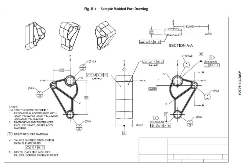
The standard is Y14.5-2009.

Thank you
 
Replies continue below

Recommended for you

Dean and Burunduk,

I understood. Then my follow up question is how would you define datum feature C in the example below if I want the MMC or LMC to be applied in the position FCF?
That particular cylinder is subject to -DFT (as per note3) and it is shown RFS.
If I want that feature (or any other feature for that matter to be modified at MMC or LMC (lets say for functional reasons), then how would you say it / show it on the drawing?

Thanks again

Have a great weekend.


c_-_Copy_pbiaby.jpg
 
Dean,

Just to clarify, the above picture, as you can see, is from Casting and Forging standard Y14.8-2009 where the FULL FEATURE modifier <FF> is not used/ introduced.
Now, let's imagine I would like to use position at MMC or at LMC for the datum feature C or for the hole found in Section A-A (instead of the shown profile).

Then adding <FF> on the position would be okay if RFS is used and would not be okay if MMC/LMC is used. I think that is your advice, didn't it?

How would YOU recommend the callout to look like if MMC/ LMC on position is to be used (with the FULL FEATURE modifier )?


Hi Kedu,

Yes, that is a figure that I have seen before. With a drafted feature that has a 2D size tolerance at one end only, I would not apply MMC or LMC. In fact, you bring up a good point. There should be a rule that prohibits modifying a tolerance at MMC or LMC if that tolerance is associated with a 2D size spec on a drafted feature. This is the case any time +DFT, -DFT, or "Draft adds material" or "Draft reduces material" is applied.

The reason for this is that the size spec applies only to the mold line of the feature which can be either inside the material on an inside corner or outside the material (in space) for an outside corner (where these corners would be visible in a longitudinal cross section of the drafted feature. There can be no surface method of evaluating these tolerances, so we should not allow it.

Dean
 
Dean,
One more question regarding the shallow recess example from my post above from 13 Jan 21 21:04.
Had the width Y been not of a feature with a circular cross-section but a flat groove cut from a planar surface, would you still consider the position tolerance a valid callout? Once again, the inner radii would not be fully formed and there would be no nice behaving planar parallel surfaces to form a width type FOS.

The reason why I suspect there might be a difference is that two parallel circular line elements may still be able to constrain the orientation of a virtual (not physical) two parallel planes unrelated AME, but a feature made of two parallel straight line elements will not be able to constrain that orientation. Then even if we draw a parallel to the spotface case, there is still an open question that remains -should the AME be perpendicular to the top, or bottom face (the bottom face is the bottom of the groove)? The difference might not be critical practically but there is some ambiguity nonetheless.
 

Dean,

I appreciate your input
Regarding those three quotes
Dean said:
I still wouldn't hesitate to apply position on a conical feature

Dean said:
I would recommend that either profile of a surface or position (without the <FF> modifier) be used if (M) or (L) is the functional case for drafted features.

Dean said:
For MMC or LMC, the functional case is that clearance/space must be available for MMC, or material must be present for LMC. Since the mating feature will not center itself within the considered feature the axis is not relevant (or not relevant enough) for these cases, the surface is the feature element that should be controlled, from a functional point of view.

then are YOU saying that there is no way to cleary specify in Y14.5 or Y14.8 (future revision with Full Feature <FF> modifier) a casting or a forging hole modified at MMC or LMC?

Lets say the casting holes get assembled with a fasterner (so MMC is the correct modifier) and we care about the entire feature (which is drafted +DFT or -DFT per its applicable process, casting or forging) we do not want to apply the position only in 2D to the mold line but to the entire feature), THEN how should I say it in a standardized language?

Or the opposite example: a drafted casting feature gets machined and material shall be present and a position / a location control is to be used, THEN how to say it in GD&T language that position is applied to the entire feature modified at LMC (again not to the mold line, but the entire feature)?
Again, LMC and <FF> are needed because the entire feature gets machined and we want to make sure the entire "as cast" material gets cleaned up/ removed


You said, you would not hesitate to use position for a conical / drafted feature, then how your position would look like in those two cases above (shown in red and in green)?

 
Back to the original topic, and the issue of the ambiguity of interpreting the UAME of a shallow or 2D hole or flat circular spotface. What about calling out the location of the spotface pattern with the MMC modifier to invoke a datum related boundary? Then the edge of the flat portion of the spotface just has to reside outside the boundary.
 
OT - ASME draft review process.

The drafts are announced here:
Given that the last new issue of Y14.8 was 2009 that means that, had one been checking for the 60 day available window, one would have less than a 1% chance of finding it, if it were the only thing released. I'd estimate about 1:10000 as closer odds if one is not on the committee, of missing it among all the others. I'm unsure that being a member of ASME would allow setting a flag to be emailed automatically. It would have cost around $1500 for that if it existed.

To be meaningful it takes at least one check per month and that cuts nearly a month off the time to review and create any submission, assuming they don't black out big chunks. There is even more time lost if they send a print copy.

Given the spastic nature of the updates it may be anywhere from 5 years to 15 years (60 to 90 months). Miss one and it could be gone without notice by the next check, leaving only a passing comment to alert anyone that it is no longer available.
 
3DDave,

To make things worse, if a new modifier (Lets say <FF>) is shown in the draft that does not mean will show up in the relesed version. Committee could change their mind and have last minute second thoughts.

What I am trying to find out from Dean is what were the reasons (I assume valid reasons) on why the committee said -"NO-NO" - to position FULL FEATURE <FF> modified at MMC or LMC for drafted surfaces (conical surfaces or wedges) with -DFT or +DFT?
It is not very clear to me why this decision has been made?
Why resticted <FF> for -DFT / +DFT to RFS only?
 
Kedu - there is nearly zero chance of such a change. To get to the draft it's gone through many votes. Being an optional feature no one is likely to mount a campaign for its removal when the response will certainly be "Just don't use it."

I'm trying to figure out what problem FF fixes, so I thought this was a current draft; hence my interest in looking for it.
 
3DDave said:
I'm trying to figure out what problem FF fixes, so I thought this was a current draft; hence my interest in looking for it.

I guess the problem to solve is: how to say in GD&T language that on a drafted feature the axis is taken from the entire conical surface/ tapered surface and not only from a 2D circle/ width.
For a drafted feature 2D size tolerance and 2D position tolerance at one end only is the default.

Do you agree with my assessment?


How different is that than any nominally circular/width feature that ends up made with a taper? The magic expanding plug stops at the narrow end and that's the UAME.

Unless there is a device that expands and changes taper to fit the feature it doesn't seem as if there is a practical application. Unless the taper is perfectly matched and the feature perfectly formed there's the opportunity for only one end to make firm contact, allowing the mating item to rattle and not create a unique axis/center plane.

I get that people want to do this, but I struggle in seeing an example where it would be used. Sure, there are precision tapers, but those are of sufficient quality as to not benefit from MMC/LMC as they are used in RFS cases. But on as-cast surfaces?

I'm sure there is a position paper that will never be released as it is part of committee deliberations.
 
3DDave,
3DDave said:
How different is that than any nominally circular/width feature that ends up made with a taper? The magic expanding plug stops at the narrow end and that's the UAME

That exactly what I've been asking before. See my quote below.
So, if there is no concern at all about UAME and is okay "as is", then my quick follow up question is:
Why in your slot definition (this link allowing position at MMC (or LMC) is not an option? Or maybe it is an option?
Otherwise stated, could you have position at MMC or LMC for that 2D conical circular element or for that 2D width ?

Kedu said:
Speaking about UAME and its definition, I would like to ask you if there is any support from Y14.5 point of view to drive an axis from a conical surface?
In other words, if a hole 10mm ±0.5 is made as 9.5mm at one end and 10.5mm on the other how reliable an axis could be driven from this "as made" hole?
I think it is not stable and UAME could not be repeated in a consistent way.


Again, I am not disputting your guys points, but trying to understand what is wrong and what are the unintended consequences of allowing the features to be modified at MMC/ LMC
 
Kedu said:
Why in your slot definition (this link allowing position at MMC (or LMC) is not an option? Or maybe it is an option?
Otherwise stated, could you have position at MMC or LMC for that 2D conical circular element or for that 2D width ?

Why not? The only difference between a 3D width/cylindrical feature and a 2D width/circle is the number of cross-sections at which the single width/diameter dimension and tolerance that was specified applies. One cross-section versus an infinite number.
For a tapered feature, there is no unique MMC/LMC, there's a different value for every cross-section. Suppose that you perceive a conical taper to be produced at LMC. Offset it in the axial direction relative to some fixed reference, and you get what can be perceived as an MMC cone. That is because cone size depends on where you measure it.
 
Thank you Burunduk,

Burunduk said:
Why not? The only difference between a 3D width/cylindrical feature and a 2D width/circle is the number of cross-sections at which the single width/diameter dimension and tolerance that was specified applies. One cross-section versus an infinite number.
For a tapered feature, there is no unique MMC/LMC, there's a different value for every cross-section. Suppose that you perceive a conical taper to be produced at LMC. Offset it in the axial direction relative to some fixed reference, and you get what can be perceived as an MMC cone. That is because cone size depends on where you measure it.

So, then why if the full feature term <FF> is added to the conical feature's position along with draft minus or draft plus notation, the callout became invalid?
I am trying to understand the subtle reasons of such approach being illegal per Y14.8.


Hi Kedu,

Sorry for the lack of replies lately. Work is thankfully super busy for a few weeks.

I think only RFS can be applied with <FF> +DFT oir -DFT (or draft adds/reduces material). I tried to explain why in an earlier comment. The 2D diameter or width has to be on the feature, not in the material or out in space, for there to be a valid application of tolerances modified at (M) or (L). Dimensions to mold lines are not on the feature, they're at an extended intersection, due to the radius around or along the end of most any drafted feature, since castings, forgings, and molded parts almost always have radii at the base and top of each drafted feature.

Dean
 
Kedu said:
So, then why if the full feature term <FF> is added to the conical feature's position along with draft minus or draft plus notation, the callout became invalid?

Sorry for not being very clear. The first (not bolded) portion of my reply is related to 2D elements. The bolded portion of my reply is related to full features and should answer your question:

myself said:
Why not? The only difference between a 3D width/cylindrical feature and a 2D width/circle is the number of cross-sections at which the single width/diameter dimension and tolerance that was specified applies. One cross-section versus an infinite number.

For a tapered feature, there is no unique MMC/LMC, there's a different value for every cross-section. Suppose that you perceive a conical taper to be produced at LMC. Offset it in the axial direction relative to some fixed reference, and you get what can be perceived as an MMC cone. That is because cone size depends on where you measure it.

I should clarify though that the part of my reply that's related to the 2D elements where I say they can be controlled at MMC/LMC refers to 2D elements located on the feature (where a cross-section is located by basic dimension), such as the slot example you were asking about. Not to theoretical intersection hanging in space such as in the cases addressed in Dean's last response.

 
Since a tapered feature is not a feature of size, by definition, there can be no MMC/LMC allowed. It has nothing to do with different values (local size) along the feature.
 
Still stuck on how "FF" rather than just defining that a taper has an axis or centerplane is required. Don't tolerances apply to the entire feature by default? Maybe the casting group is using the new symbol as a political workaround to avoid the D&T committee?

Resolving tapers to cylinders and widths should be allowable. In yet another oversight by the committee one can specify the MMB explicitly for a datum reference, but not for a geometric tolerance; a similar error to being able to specify a tapered feature as a datum feature, but not use the same construction to derive an axis or centerplane as part of a feature's geometric tolerance.
 
Status
Not open for further replies.
Back
Top