Continue to Site

Eng-Tips is the largest engineering community on the Internet

Intelligent Work Forums for Engineering Professionals

  • Congratulations KootK on being selected by the Eng-Tips community for having the most helpful posts in the forums last week. Way to Go!

Locating Timing Pulley Tooth to Keyway 2

Status
Not open for further replies.

donatim24

Mechanical
Jun 13, 2018
27
I was looking at one of our drawings and we have a drawing for a timing pulley that requires the centerplane of a particular tooth to be aligned to the centerplane of a keyway within 0.5 degrees. Currently, the requirement is that the centerplane of the tooth is aligned to the keyway and not the surface of the tooth. I assume this is because the tooth form and size are controlled by the selected profile for the timing pulley.

The tooth profile is AT10. Therefore, there are no opposing planes that can be used to derive a centerplane. Is there an established way to determine the plane, or is the dimensioning approach flawed?

Best approximation of the requirement:
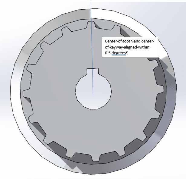
Timing_Pulley_Question_keaysf.png
 
Replies continue below

Recommended for you

3DDave,
What if the center plane of the tooth (suppose it's determined by some agreed-upon method) measures very close to 0° from the reference plane, but is produced with a considerable offset from it? Do you consider it acceptable for alignment? If not, how do you expect a tolerance in angular units to detect that?

Moreover, how do you expect the reference plane for the angle measurement to be interpreted and established? Is it OK if it's based solely on the keyway, or should it also bring the axis of the bore and a mating planar face into play? If the latter, the OP might as well do it properly and specify a feature control frame with reference to the datum features that constrain that part in the assembly, with consideration of datum precedence order.

Or would you rather suggest providing ambiguous requirements supplemented by an inspection plan to the vendor?

That's how geometric tolerances are defined - the tolerance zones are in linear units, not angular units. If you insist on controlling alignment in angular units, there should be some special failure prevention methods performed, like functional tests, which are likely to be more expensive than geometric tolerancing and the appropriate inspection methods.
 
You see - that's the root of the problem. Y14.5 is dedicated to cartesian systems and is not appropriate for angular ones, yet some feel the need to cast every problem into a Y14.5 straight-jacket.

The rest of the world already handles polar systems without the need for Y14.5, but go ahead and set the ignition timing on your car with a profile tolerance.

"Unit of angularity tolerances per ASME Y14.5-2018 is linear length (in. or mm)."

Yes - that is true, but that is "angularity (TM)," not "angle". The ASME redefined angularity in a narrow way that really is either another form of profile tolerance when applied to surface geometry and a limited form of non-angular zone control to derived geometry. This makes it easier to handle with a CMM, but does not represent the requirement of an angular tolerance zone.
 
"What if the center plane of the tooth"

Nothing is driven by the center plane of the tooth. Stop recasting the problem in terms that you feel support your argument. Gear tooth location is always measured along the pitch arc. The shape of the tooth is controlled by pitch error that may include form and runout, but in ways that neither is typically measured per Y14.5, and that is based on the mounting bore, just like always.

No answer for suspension or other timing alignment? However does the rest of the world cope.

"That's how geometric tolerances are defined"

That's how Y14.5 defines their take on geometric characteristics, but there is no rule those characteristics apply to this case.
 
Here's what one might do. Establish the bore as a datum feature along with two points on the pitch circle to establish a datum reference frame.

The task - apply a limit to the clocking, not offset, of the slot, using the limit expressed in degrees as that is what the system requirement limit is expressed in. No fair using a calculator to convert angle to any other units. You can use a tiny value for the position tolerance to locate the slot relative to the bore.

Can't customize and leave rotation unlocked.

Better. This might be a blank and the bore and keyway will change for each order, but the angle tolerance won't. Pick a linear value for the angular tolerance that will always work.
 
3DDave said:
Nothing is driven by the center plane of the tooth. Stop recasting the problem in terms that you feel support your argument

These are the OP's terms, not mine:
"Currently, the requirement is that the centerplane of the tooth is aligned to the keyway".
 
jassco said:
Unit of angularity tolerances per ASME Y14.5-2018 is linear length (in. or mm). That is because Cartesian coordinate system is used on most of CMM machines.

Angularity in linear units has been the case ever since this geometric charactersitic exists. Long before CMMs became wide-spread, and before they were even invented.

The classic sine bar and height gage measurement of angularity yields results in linear units.
 
"there are no opposing planes that can be used to derive a centerplane"

Also the OP.

Angularity has been in angle units for thousands of years, long before the sine bar was invented. For certain a sine bar can be used as a means to compare slopes, angular units, so that method is available.

Answer the question. The requirement for tolerance is in degrees. How does Y14.5 allow that acceptance range? Millions of gears are already made with this consideration, so some method must be working.
 
3DDave said:
"there are no opposing planes that can be used to derive a centerplane"

Also the OP.

This is why the OP got the suggestion to use the keyway and not the tooth as one of the datum features and control the tooth by profile relative to a datum reference frame that uses it. It's more functionally appropriate anyway. Another option, the first one that I mentioned, is a simultaneous requirement of a profiled tooth and the positioned keyway, probably relative to a datum reference frame that is based on a mating face and the bore, if the tolerance accumulation can be tolerated.

3DDave said:
Answer the question. The requirement for tolerance is in degrees. How does Y14.5 allow that acceptance range?

There is no unambiguous way to specify that range in degrees, neither per Y14.5 nor per ISO 1101 and the bunch of other GPS documents. That is why the OP got the suggestions to use the more robust methods. Degree tolerances are mainly OK for chamfer angles that are of little concern to quality.
 
Gear timing, automobile suspensions, locating astronomical features billions of light years away, the location by GPS of places on the Earth, clockworks. All of them, per you, ambiguous? None use ASME Y14.5 or ISO 1101, by the way. By that, even using a sine bar must be ambiguous; no possible way to know that angle it produces.

The tooth will be in place before the keyway, making the tooth the desired datum feature - specifically with a datum target on the pitch diameter. But then there is the inadequacy of Y14.5 to manage this timing requirement for a rotational tolerance.

The installed use depends on the angle, not a profile, so the control of the angle (not angularity (TM)) is what is required.
 
All your examples are irrelevant. Angle measurements have a place in science and engineering, it's just currently not a good way to specify dimensional limits for mechanical components.

There is no standardized way to specify variation in degrees, radians, minutes, seconds or whatever angular units relative to a datum reference frame, while a datum reference frame (or a system of datums per ISO GPS) is the only rigorous way to control feature relative to the part's interface to the rest of the mechanism. A tolerance analysis determines the allowable variation in linear units and that should be used to assign geometric tolerance values.

If you think that something needs to change to allow meaningful tolerancing in degree units, you are free to get to your local post office and send a letter to the ASA Y14.5 committee.
 
Since it works, it is a good way.

"A tolerance analysis determines the allowable variation in linear units and that should be used to assign geometric tolerance values."

That is certainly going to suck for a tolerance analysis on angular variation accumulation.

Since when is metrology not part of science or engineering?
[project]=1181

What's "ASA"?
 
If it worked, there would be no trouble such as the cause of this thread. It's typical that when similar problems occur, people look for solutions in geometric tolerancing.

Your first link leads to an error page.
The second link downloads an article in which one of the first statements is:
"The ability to measure angles is needed for the measurement of machine
geometries such as straightness, flatness and parallelism of surfaces"
Is that AI-generated?

ASA stands for American Standards Association, an early incarnation of ANSI, that published the first edition of the Y14.5 standard in 1957. Since the method of controlling orientation in linear units is rooted at the very beginning of international standards on dimensioning and tolerancing, that's where your complaints should have been addressed.
 
By that measure Y14.5 never works, just based on the number of threads questioning it.

Yup. The basis for all those other measure is measures of angle. The fundamental measure. So fundamental there hasn't been a need to standardize until we get to the nRadian range.

I have no complaint about the existence of a tool you would use inappropriately.

Sorry the forum software clipped the link in a way that you are unable to deal with. The difficult to use.

Let me reformat to make it so you can get it to work - copy and paste the second line to the end of the first.


?tx_eurametctcp_project[project]=1181
 
There is no angle measurement in the process of flatness, straightness, and parallelism evaluations. Even a sine bar in its common use does not measure an angle. The angle is set up but not measured. In your own words: "By that, even using a sine bar must be ambiguous; no possible way to know that angle it produces." So no, angle measurements are not the basis of everything, and are mostly unnecessary for mechanical components, in the context of the tolerances that are typically specified in an engineering drawing or data set.

Angles can be used in calculations to assign (linear) tolerance values, but are not useful for specifying orientational variation ranges in a way that requires obtaining measured values in angular units.

In every place where a directly toleranced angle is a requirement, it is ambiguous how to obtain the polar coordinate system in which the angle will be measured, and multiple measured angles may be considered as representing the actual as-produced geometry.

There is no shortage of examples of parts being made for years despite ambiguity in their geometric requirements documentation. That does not mean ambiguous solutions should be proposed where there is already a clear indication of a problem with an existing ambiguous solution.
 
"By that, even using a sine bar must be ambiguous; no possible way to know that angle it produces."

is mocking you to show how far from correct you are in using a hammer to solve a problem for which a hammer is the wrong tool to choose.

 
The wrong tool is the one that already failed for the OP:
"The current dimensioning scheme is based off an angular tolerance with no GD&T applied"
 
When you tell me you cannot measure an angle I believe you.
 
I believe you when you indicate that you don't understand that any angle measurement is only a rough estimate of the orientation of an actual 3-dimensional feature.

Specify 0.5° MAX or +/-0.25°, and there are no single solutions for a measurement reference, a tolerance zone, or a measured value.

There may be one measurement solution for that type of requirement, out of multiple possibilities, that you would consider correct. If you would provide a measurement plan as part of your design specification, you are free to keep at that, and you should have included that in your suggestion to the OP. You didn't, and that's wrong. But even if you did, it's not effective tolerancing and bad advice.
 
The requirement is +/-0.5°

As long as you present no alternative and simply attack the working solution, nothing will make you feel any better.
 
"Within 0.5°", as the OP stated, is not +/-0.5°.
+/-0.5° would be "within 1°".
You made a typical beginner's error. See how big the problem with directly toleranced angles is? You can't even interpret the variation limits properly.

I offered an alternative to the current scheme. The current scheme of an angular tolerance doesn't work, or the OP wouldn't bother.

Come to think you haven't offered any solution at all, you are mainly just attacking mine.
 
Status
Not open for further replies.

Part and Inventory Search

Sponsor