Continue to Site

Eng-Tips is the largest engineering community on the Internet

Intelligent Work Forums for Engineering Professionals

  • Congratulations KootK on being selected by the Eng-Tips community for having the most helpful posts in the forums last week. Way to Go!

Long Span (35') LVL Beam Design 8

Status
Not open for further replies.

Brobocop

Structural
Dec 27, 2019
17
I was contacted by a building owner that wanted to build out his attic space into offices, and needed to ensure that 2 installed beams (Beam were never previously Engineered) are adequate to handle the additional live and dead loads.

There are two beams in question, each comprised of Four 2x16 LVLs fastened together and 35 ft in length. They are supported at the ends by two 5.5"x5.5"x0.25" Square HSS. The rest of the ceiling is framed laterally with 2x10s 16" o.c.

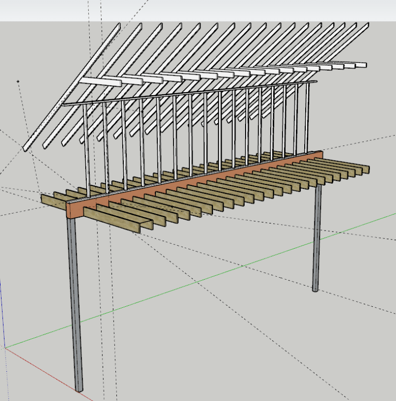
Rather than Model the entire building, I modeled just column/beam frame (diagram attached), and am wanting to put the distributed dead, live and wind load on the beam for my analysis.

My STAAD model results are currently showing Fail, and also a mid-point Deflection of about 3" (L/140).

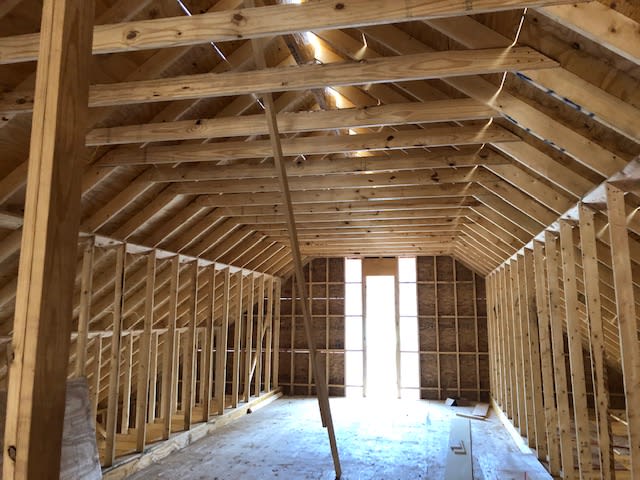
Looking at the roof framing, is the rafter bracing wall - that sits directly onto the beam - picking up much load? or does most of the roof load go to the exterior walls? I'm making sure I'm accurately calculating all loads before recommending a different solution (Being that the beam is currently installed).

35' is a heck of a span to begin with. Not many LVL manufacturers have spans listed that high in their literature.

I appreciate the insight.
SketchUp_rz1hue.png


STAAD_Model_dt91y0.jpg


Beam_2_arlg2u.jpg


Beam_3_pj6cfk.jpg


Beam1_bqregw.jpg


Looking_South_West_pybuje.jpg


Looking_North_oyduyx.jpg
 
Replies continue below

Recommended for you

You could analyze one rafter with/without the wall acting as support. Can the rafter support the weight without the wall support? Is the wall support helping reduce the rafter beam span? Determine the support contribution following that sensitivity analysis

It appears as if the slope is close to 1:1. My inclination, based on the pictures, is that the wall is supporting some vertical load and whatever wind is hitting that roof.
 
Can't you check the beam by hand calculation? Then you'll see which load is excessive. Or label the loads, then read STAAD summary report on each load.
 
I'm not super familiar with this kind of system, but what would those walls be doing if not supporting vertical load? They can't take horizontal load, and if they are acting as bridging, only the top plate would be needed, not the vertical studs, right?
 
I think they are definitely supporting vertical Load. I actually made a truss model of one rafter system with both vertical members and the lateral 2x6 brace.

They are using this space for a single office. Is a LL of 80 psf required, or could it be lowered to 50?
 
Check your local governing code for appropriate live load.
 
Yes, the wall will carry the roof load. The rafters don't look like they could carry the roof without the wall.

You could use 50 psf LL for the office, but I'd expect that deflection will still be an issue.

(you didn't ask this, but also be sure that the 4 LVLs are fastened together sufficiently.)
 
Brobocop said:
Four 2x16 LVLs fastened together and 35 ft in length.
I'm accurately calculating all loads before recommending a different solution...
I appreciate the insight.

Save yourself time and "hand-wringing" over how to precisely apply the loads. In all likelihood the floor will fail because of excessive deflection from even the most basic loads. The reason, consider the LVL's span-to-depth ratio (420" / 16" ≈ 26). Any ratio over about 20 begins to act like a "flat spring" which will make the floor's serviceability seem "bouncy" to occupants. This is not magic, it's about a beam's moment of inertia which is sensitive to beam depth. This floor will be even worse, because both ends of the floor joists will be supported by bouncy, low moment of inertia LVLs.

Don't take my word for this, make the calcs using only known dead loads, and the 50 PSF floor live load (forget about wind load for now).
What do you get... deflection > L/360, I'll bet?

FWIW, span-to-depth ratios are a great first check for any beam, wood, steel or concrete... because, for deflection, moment of inertia is more important than material properties.

[idea]
 

Fantastic. And you're absolutely right. The deflections would not meet IBC or ASCE limits.

So now comes the fun part. What is the solution here? Is it simply to not occupy the attic?
If they are dead-set on utilizing the attic, I immediately think of 2 options:
1. drop another 5x5x0.25 column mid-span.
2. Rip out the LVL, and install steel beam. Probably W14 or greater.

Can they modify the existing timber section? Or go with a larger LVL?

You're absolutely correct. The contractor liquid nailed them together, which is not per manufacturers recommendation, or code. No sense in addressing this at the moment if the beams are not sufficiently sized.
 
Just curios:

1) Can you increase the beam depth by built-up with selected wood. Another 4" will help a lot.
2) Can you add kicker (short diagonals) at floor below, from rafter to post/wall stud, to divert the load, and shorten the rafter span.
 
Brobocop said:
1. drop another 5x5x0.25 column mid-span.
2. Rip out the LVL, and install steel beam. Probably W14 or greater.

1) IMHO, that's best... by far. Nice thing is that the column does not have to be at midspan. The idea is to reduce the span, exact span lengths are not critical. Spans of , say, 16' and 19' should be be fine. Another factor in favor of this solution... a continuous beam is inherently "stiffer" than the same beam used for equivalent simple spans.

Also, if near-mid span locations are not convenient... use two columns, maybe closer to LVL ends. The three continuous spans can be more or less arbitrary lengths as long as none of spans are "too" long.

If you do add column(s), carefully look at loads on them. Added columns will be interior supports on a continuous beam. Loads on supports at those locations will be noticeably higher than they would be for simple span supports. You may have to install appropriate column footings.

2) A W14 has a span-to-depth ratio of 30 (420" / 14"). Reread what I told you about desirable span-to-depth ratios.
For steel, I would start looking by looking at W21 (span-to-depth ratio of 20) or maybe W18 (span-to-depth ratio of 23). In any event those are just educated guesses to get started - the calcs should be the basis for a decision... not Engineering Judgement.

[idea]
 
[URL unfurl="true" said:
https://www.eng-tips.com/userinfo.cfm?member=SlideRuleEra[/URL]]

Is there any potential retrofits to the existing Timber beam that would work? Maybe building up the section to have the 21” depth?
 
Here is what I would do (assuming the numbers worked out)....
Cut off 24" of the kneewall and add a 4-ply, 24" LVL on top of the existing 4 ply beam. Strap them together and add kickers down to the floor system to brace the top flange of the new beam.
 
So now you would effectively have a 40” deep LVL beam?
 
I don't understand the concept of "add column in mid-span", while it relief the beam from load, where the footing is - a level below?
 
If a column were added, the foundation would need to be modified/analyzed for sure.
 
A "change of use project" becomes full house renovation? Better to look for other solutions. :)
 
Also, add a column anywhere will reduce beam span (L), as now it is a two spans continuous beam. Beam depth and deflection likely would not be the problems.
 
The problem is these beams were never designed to begin with, and are undersized even without the additional live load or “change of use.”
 
Sorry to crossed your response. See my edited text in red above.
 
Status
Not open for further replies.

Part and Inventory Search

Sponsor