Continue to Site

Eng-Tips is the largest engineering community on the Internet

Intelligent Work Forums for Engineering Professionals

  • Congratulations waross on being selected by the Eng-Tips community for having the most helpful posts in the forums last week. Way to Go!

Long Steel Ridge Beam in Residential 4

Status
Not open for further replies.

Buleeek

Structural
Sep 5, 2017
98
Hello,
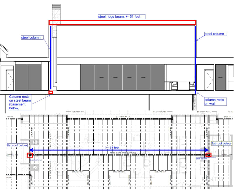
I am working on a residential house with a very long (51 feet) steel ridge beam (cathedral ceiling). The gravity loads are +- 500 plf. I am looking for some opinions on how to properly connect the steel members to each other and if there are any other things to consider when such a big and long beam serves as a ridge beam in a residential home (deflection, overall stability, etc). See attached. Thank you.
 
 https://files.engineering.com/getfile.aspx?folder=9e80af2c-f2e7-4db1-ad42-61d29a541c05&file=steel_ridge_beam.jpg
Replies continue below

Recommended for you

There are a number of things to consider, including deflection, LTB, adequate connections, etc.

Are you the PE stamping the structural drawings?
 
Wow, that is long. 40 ft. is the longest I have ever done. You are in the 24 - 27" beam range. My biggest concern would be a residential contractor trying to erect something like that without incident. It would likely have to be temporarily braced along the span until the rafters and, ideally, the sheathing was installed.
I would keep deflection at 1.5" or less total load.
 
Thanks for advice. The beam results are provided in the attachment. The beam is assumed continuously braced by rafters.
- What shear connection to column would you propose? Or, would you advise a moment connection to column?
- I don't necessarily have room for W-shape column, so I am thinking 6x6 HSS.
 
 https://files.engineering.com/getfile.aspx?folder=17a20350-7f1c-430b-be66-00a75de30a43&file=ridge_beam_results.jpg
What is your design reaction for this member, and what does the foundation design look like to resolve this reaction? How confident are you that the contractor would be capable of layout out reinforcement correctly, is there something you can do to simplify foundation design and limit settlement?
 
The reaction is not big: +- 15 kips. One column sits on the basement concrete wall, the other will sit on a steel beam located in the basement ceiling.
I think the reaction is not a big deal in this case, more a stability, potential thrust cased by deflection (+-1").

Thanks,
 
Beam continuously braced by rafters..... I've got to wonder about that, plus if there's net uplift is the bottom flange of the beam braced or not?
 
Would be interested to hear the justification on taking restraint from the rafters?
 
Buleek said:
potential thrust cased by deflection (+-1").

This has been discussed many times in previous threads. Most do not worry about this.
If you are worried about uplift bottom flange stability, you could add collar ties directly below the beam and attach them to a nailer bolted to the bottom of the beam.
 
I have to say, this sounds somewhat suspect. W27x94x51'-0". That is a massive beam for a residential roof. I would say this better be an ultra, high-end house ($$$), otherwise this is probably not a good idea at all, mainly because the builders involved will be utterly clueless and inexperienced with steel construction on this scale and will, therefore, totally screw this up and screw you over. You intend to brace the top flange with wood rafters. I would be leery of relying on wood connections (and lousy framers) to brace something on this scale. What about the bottom flange in case of uplift? You ask a very basic question, like what is the best shear connection to the column? My 1st choice would be a single plate connection, but it could be any number of standard connection configurations. How will you brace the columns at each end?
 
I'm curious about the 500 PLF gravity load...not sure what all is included in that number (Is that dead load + live load??).
Maybe the house is in Florida so not much snow but then, issues relating to uplift might be something to consider more.

As far as the beam to column connection, just about any standard steel connection should work fine. Columns aren't going to be nearly as stiff as the beam so moment connections doesn't seem to be worthwhile.
Beam bearing on top of the column is probably the "least redundant" as far as beam stability goes.

Looks like a 5000 lb beam and it's way up there. Def want to be sure the builder is accustomed to that sort of thing. Temporary bracing of the column and beam assembly will be an important consideration.

I'm not sure the beam bracing is such an unlikely problem. I'd expect the rafters to be framed into solid wood blocking that it bolted to the web and it seems like you might be able to detail a top plate on the steel to have the plywood sheathing attached to it. I definitely would want blocking bolted to the top flange and the web and all rafters connected with joist hangers. Not sure how deep the rafters are but with a lot of insulation, you might have something 14" tall or more. Even wit 2x12's, if they are steeply sloped, you'll have a decent amount of contact length. Looks like a shed roof over 25+ feet on the one side so... want to be sure the rafters are well connected to the beam.

Looks like stress is not very close (deflections controls theses things usually anyway).

Really wonder about the "stability" of the steel columns. I assume they are buried within the framing of some sort of end walls??

Pretty big space, I'd wonder about the shearwall design and how to get the wind loads into the end walls. I'd want to make sure the columns are well connected to the end walls. I'd probably thru bolt 2x6's so the sheathing attaches full length.
 
Longest ridge beams I've looked at would be in the realm of 35-40' (10-12m)
I don't like using long span ridge beams as you introduce problem upon problem

- It's a huge, expensive piece of steel

- Thrust is very difficult to control and the builders will probably end up chasing problems the whole way through the structure
This is particularly problematic for your building where you have the huge opening with the LVL beam...you're going to get asymmetric deflection profiles and all sorts

- It will be very deep so architecturally challenging to deal with

- Transport will be a nightmare

- Erection will be a nightmare

- No redundancy

- Detailing for restraint etc becomes very critical

Instead, I typically break the span up with portal frames (which are often needed for lateral anyway)
In your case, the ginormo LVL adds to the challenge but I'd be looking at putting in a steel portal frame either side of that where you have the double rafters
This looks like it'd cut your span down by ~40% so still large at 30' but more manageable at least
You could look at bolted flange plates or something to achieve some continuity over the portal frame
 
For a cathedral ceiling like this, I don't think a large steel ridge beam like this is necessarily a bad solution. I suppose a 4-piece steel portal frame is another option, but that seems like more work overall. Still, not a bad idea. If I was concerned that the cost could be an issue for the owner, I would try to alert them of that early on. Other options are scarce: adding columns, adding a flat ceiling, or some strategically placed trusses (which usually look fine and don't really affect the open space). Personally, I think 6 exposed wood trusses at the double rafter locations would look cool, but then again I'm not the architect or owner.

I wouldn't be worried about the thrust due to 1" of deflection in the beam. Perhaps a slight camber could be beneficial to help a little with that.

I also wouldn't be worried about lateral bracing of the top of the beam as long as rafters are framing into it (which they must be). If there will be net uplift, then perhaps there should be some bottom flange bracing, but it shouldn't be a big deal because they'll probably need framing at the bottom of the beam anyway to create a short section of flat ceiling at the top.

Personally, unless I knew who the builder was going to be for the project, I would just assume that somebody competent will be constructing the project. Some residential builders are entirely comfortable using steel, others will avoid it and refuse the job, others will take the job and sub the steel erection to somebody else, and yet others will screw up the whole thing somehow, like using a 2-ply LVL in place of a massive steel beam like this.

How the steel is erected shouldn't really be your concern, although I suppose a shear plate connection might offer better stability during erection. In that case, you might want to include some eccentricity in the column design (another common discussion here).
 
Is there some reason a somewhat normal scissor wood truss isn't viable here? As I recall the file that was posted was... never mind nobody posted the original image as an in line image.

So here it is for everyone to more easily see...

steel_ridge_beam_e51bwq.jpg


What about some sort of special profile open web steel joists versus this steel ridge beam approach that seems a bit less common, if nothing else, with the attendant load transfer status and bracing questions?
 
Agree with Eng16080 - in the end it's a beam guys, I think we can handle it and the contractor should be able to as well or not take the job. Are there nuances? Yes, limit the deflection as XR suggest, consider the rafter slope and corresponding lateral displacement at the eave. I do wish AISC had some guidance on continuous bracing conditions in Appendix 6, I've attempted to put some numbers to the point bracing equation by spreading it out over some distance, but this always feels a bit arbitrary. Generally, regularly spaced wood framing with attached diaphragm is considered to laterally brace a steel beam in my experience.
 
When using the equations in appendix 6, looking at this beam as continuously braced probably isn't a great idea. The shorter the unbraced length gets (whether you use diaphragm fastener spacing or rafter spacing), the higher the required stiffness gets. Especially for a beam of this size, you'll exceed what a wood sloped diaphragm and/or wood rafter can do pretty quickly. So I'd find the L[sub]b[/sub] that you feel comfortable using with the bracing equations and design the beam to that.

For most steel beams in wood, I agree that the diaphragm is enough. But I would call this one a special case and pay a lot more attention to the details.
 
Do any of the AISC design guides illustrate the stiffness requirements for continuous beam bracing? I have Design Guide 28, but that is in reference to continuous column bracing.
 
Not that I'm aware of. Just Appendix 6 in AISC 360. You don't really have 'continuous' beam bracing...there's always some discreet spacing that can be used. Fastener spacing for diaphragms is common, spacing of secondary framing is also used often, stud spacing for composite beams.
 
OK OP - How did this turn out?

I'd love to see a cross section of the building AND the beam with rafters connected. That'll go a long way to advising on how to make the bracing connection viable.


Status
Not open for further replies.

Part and Inventory Search

Sponsor