Eng-Tips is the largest engineering community on the Internet

Intelligent Work Forums for Engineering Professionals

  • Congratulations waross on being selected by the Tek-Tips community for having the most helpful posts in the forums last week. Way to Go!

Longitudinal Shear Flow on Elastic Stress Distribution 3

Status
Not open for further replies.

FMPJ

Structural
Aug 10, 2020
11
0
0
GB
pic.jpg_zvmyf9.jpg


Hi Folks,

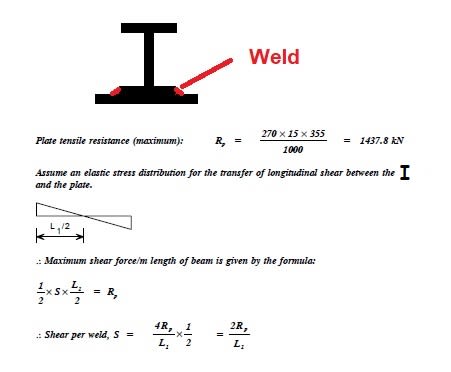
Anyone could please explain the principle shown on above screenshot.
I'd like to understand the relationship between the maximum longitudinal shear and maximum plate tensile resistance when assumed elastic distribution stress.
Thanks for your help.

Best Regards,
JPMF
 
Replies continue below

Recommended for you

retired13 said:
My message is there, so stretch this discussion will not change anybody's mind. I stay with the proven method of VQ/I, ang My/I.

Those expressions are correct within the elastic range. Q = A*y where y is the distance to the middle of the plate. It is the same y in My/I which is the fibre stress at the middle of the plate in the elastic range. My/I is the average stress in the plate in the elastic range but not beyond.

Beyond the elastic range, the plate may be stressed to Fy throughout its thickness. The maximum plate tension is T = A*Fy. The only way T can be sustained at midspan is to have a weld at each end with a total shear resistance of T.

To design a uniformly loaded simple span beam with bottom plate using LSD (in Canada) or LRFD (in USA), the welds each side of midspan must be capable of resisting a longitudinal shear of T. This means a unit shear of S = 4T/L at the supports, varying linearly down to 0 at midspan.

To use elastic theory in the plastic range is a misapplication of theory and errs on the unsafe side.

BA
 
It is the same y in My/I which is the fibre stress at the middle of the plate in the elastic range. My/I is the average stress in the plate in the elastic range but not beyond.

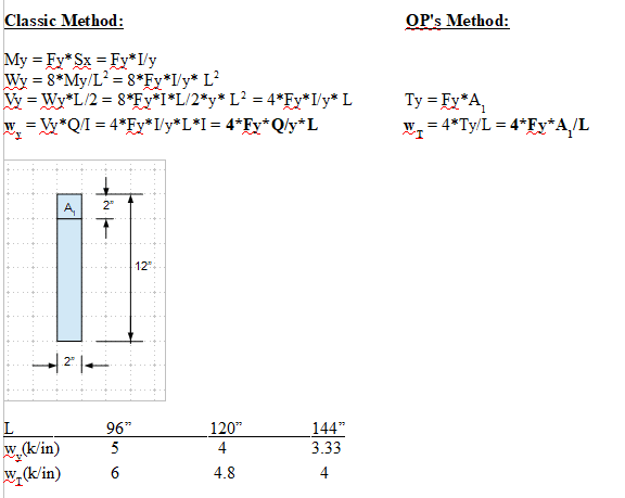
This is what I can't agree. Stress at any point of the cross section is calculated by σ = My/I, for maximum bending stress to occur, the y is measured to the extreme fiber, and the stress varies linearly from the maximum at the extreme fiber to zero at the neutral axis. Think about this: M[sub]max[/sub] = Fy*Sx = Fy*I/y, therefore, y must be a maximum. Below is my simple calculation FYI.

image_nf5tsh.png


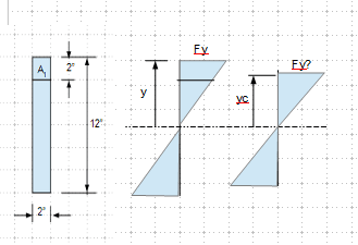
Note w[sub]y[/sub] = 4*Fy*Q/y*L = 4*Fy*A[sub]1[/sub]*y[sub][sub]c[/sub][/sub]/y*L = w[sub]T[/sub]*(y[sub]c[/sub]/y). y[sub]c[/sub] is measured to the center of element A[sub]1[/sub], y is to the extreme fiber.

Alternatively, you may want to try using plastic sectional property, that might match your concept (Fy on entire cross section).
 
retired13 said:
This is what I can't agree. Stress at any point of the cross section is calculated by σ = My/I, for maximum bending stress to occur, the y is measured to the extreme fiber, and the stress varies linearly from the maximum at the extreme fiber to zero at the neutral axis. Think about this: Mmax = Fy*Sx = Fy*I/y, therefore, y must be a maximum. Below is my simple calculation FYI.

The formula in red assumes elastic stress distribution throughout the built-up section. With a 2" x 12" plate on the bottom, y[sub]max[/sub] and Sx[sub]min[/sub] would be at the extreme fibre of the top flange of the beam, and the stress on the bottom plate would be much less than Fy. The Classic Method indicates My = Fy*Sx but Sx would be Sx[sub]min[/sub] at the top of beam, not at the bottom of plate.

Using Limit States Design (LSD) or LRFD, the OP recognizes that the plate can reach yield stress at midspan throughout the plate thickness (unless the neutral axis is within the plate) because Mp = Z*Fy where Z is the plastic modulus. The OP's method is consistent with current structural analysis methods.

BA
 
Moment is taking over the entire cross section. The composite neutral axis is right on the center, so y = 6" T & B, Sx is the same T and B. Without consider buckling, the maximum elastic moment capacity is Fy*Sx. If you back track your V , w, and get the corresponding M, then calculate the stress by σ = 6M/bd[sup]2[/sup] = M/Sx, you will see my point.
 
Let's check moment capacity for these two cases.

1. Classic Method
Force couple, F = Fy*6*2/2 = 6Fy
Lever arm, a = 8"
My = F*a = 48Fy

2. OP's Method (your thinking)
Find stress at extreme fiber, let Fy/yc = Fy'/y ----> Fy' = 1.2 Fy
Force couple, F' = Fy'*6*2/2 = 7.2Fy
Lever arm = 8
M' = 7.2Fy*8 = 57.6Fy

M'/M = 57.6/48 = 1.2 = y/yc
 
We were talking about a W beam with a plate added on the bottom. I thought you were proposing a 2x12 plate welded on the bottom of a WF beam. I misunderstood. You seem to be talking about a 2x2 square bar welded to a 2x10 rectangular section to form a 2x12 rectangular beam.

If that is correct, Mp = Z*Fy = [bd[sup]2[/sup]/4]*Fy = 72*Fy
σ = Fy; Ty = Fy*A[sub]1[/sub] = 4Fy

S = 4Ty/L = 16Fy/L

If Fy = 36 ksi and L = 96", then S = 6k/" at support
check: total factored weld shear = 6/2*96/2 = 144k =4Fy okay!

Conclusion: the OP's method is correct.

BA
 
We are on two different orbitals - plastic vs elastic. Forget about it, there is no comparison then. But kind of surprise that shear flow by plastic analysis is only 20% greater than result from elastic analysis.
 
retired13 said:
But kind of surprise that shear flow by plastic analysis is only 20% greater than result from elastic analysis.

It is actually LESS for plastic shear flow, compared to [EDIT than] elastic shear flow.

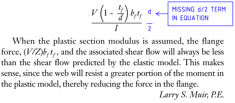
From AISC MSC 'Steel Interchange' of July 2014: Link

With the following formula correction:

shear1_yp9bom.png
 
Retired13 & BAretired glad to read your comments and the knowledge sharing is a key for growth.

OP’s formula is assuming elastic analysis which makes sense to me because when welds are tested, they behave in a relatively brittle fashion – at least they are not as ductile as the plate.

Best wishes,
JF
 
Different orbits, I agree...plastic vs elastic.

retired13 said:
But kind of surprise that shear flow by plastic analysis is only 20% greater than result from elastic analysis.

Not true. In elastic analysis, the extreme fibre can be stressed to only a fraction of Fy, not Fy. Limit States Design has replaced Working Stress Design in Canada, but as I recall that fraction of Fy used to be about 2/3. ASD in the USA may allow a higher fraction today in order to get it in closer agreement with LRFD, I'm not sure. I don't know the AISC code, particularly the sections dealing with ASD.

BA
 
Ingenuity,

Thanks, that make sense.

Sanity check for plastic moment capacity, Mp = FySp = Fy*b*d[sup]2[/sup]/4 = Fy*2*12[sup]2[/sup]/4 = 72Fy
Mp/My = 72Fy/48Fy[sup](*)[/sup] = 1.5
(*) - My edited for missing multiplier
 
On the other hand, it all seems a bit moot because, if the bottom plate is only needed in the middle section to resist moment, there won't be any weld in the end regions.

BA
 
It depends on the function of the plate, cover plate can be used for deflection. Weld is designed per shear flow, which is maximum at the beam end. You can use partial length cover plate if the moment is the sole concern.
 
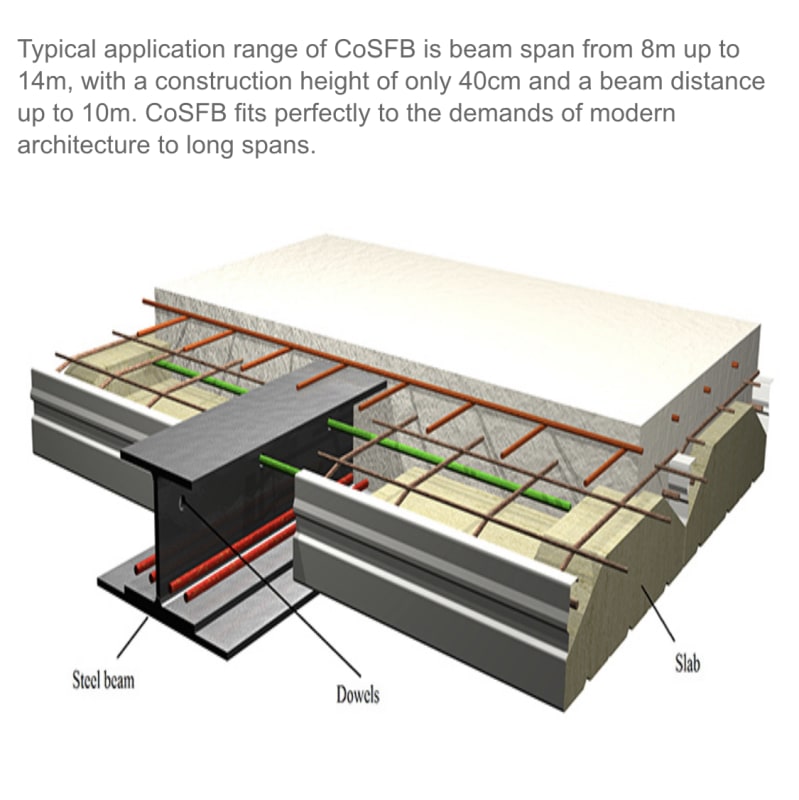
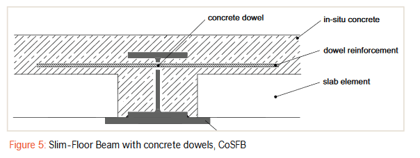
I hate acronyms. I didn't know what CoSFB meant, so looked it up. It means Composite Slim Floor Beam. That is not familiar to me and I would have to think about it for a while.

Looks like there isn't any fire cover in the picture below. I think you may be correct, retired13. This could be strictly for deflection control, which means that the structure is not relying on the beam and cover plate to sustain the loads. I will have to do some more reading on the system...very interesting.


image_ph6o8f.png


BA
 
For 15" thick solid slab, ACI recommends a clear span of 15*33/12 = 41.25'. The above solution seems too complicate and expansive.
 
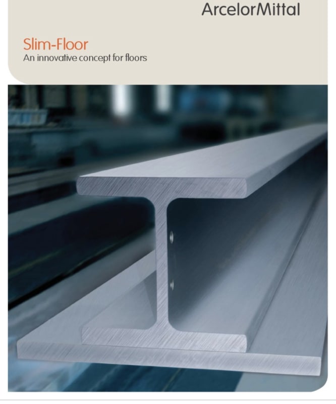
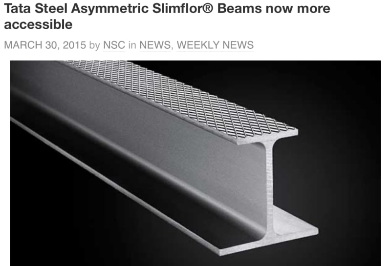
Yes that’s right BA. Those compound sections known as “Composite Slimfoor Beams” are a cost-effective shallow floor construction solution ideal to minimise floor depth.
I’m based in Europe and those members are very common in car parks multi-storey, hospitals.

B33030B6-363B-4FB6-8500-38A02F2A71C2_bla7rf.jpg
D5066E94-D8AA-4D7F-8766-BF43D194C57A_ntz28l.jpg
 
While the thinking of the flange-web connection has less shear flow demand when the section has plasticized is plausible, further look into it - isn't the section must undergo elastic stage to get into plastic range? Also, the hinge will not form everywhere on the span. So I think LRFD guys should develop a more realistic method for weld design, or just use VQ/I, which is justified by the fact that a LRFD beam will be capable of carry more load than beam designed by elastic method.
 
Status
Not open for further replies.
Back
Top