Continue to Site

Eng-Tips is the largest engineering community on the Internet

Intelligent Work Forums for Engineering Professionals

  • Congratulations KootK on being selected by the Eng-Tips community for having the most helpful posts in the forums last week. Way to Go!

Looking for ideas on a DC disconnect. 1

Status
Not open for further replies.

itsmoked

Electrical
Feb 18, 2005
19,114
I'm looking for some ideas from the Brain Trust.

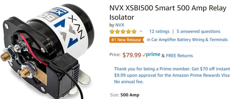
I'm building a high energy off-grid power source. It has lithium batteries. Of course the finicky lithiums cannot be over charged or over-discharged or charged when too cold (on pain of death to lots of things including one's wallet) The system's Battery Management System (BMS) needs the ability to cut the power to and from the batteries. Commonly used for this are the typical power solenoid relays:
Battery_Solenoid_wwa5b4.jpg


But those are abhorrent because they consume a ton of energy just being kept closed. They typically are too hot to touch making them scandalously power wasting. Not doing that.

Much much better is a motorized disconnect that ceases to draw any power after it's open or closed.
I use these cool valves frequently. Look at the price for a stainless steel ball valve version!!

Motorized_ball_valve_cuet38.jpg


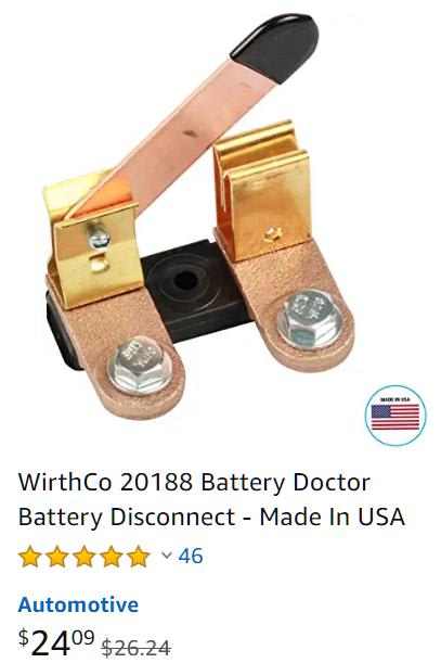
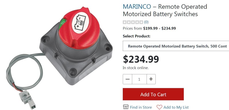
Amazing! So now turning to switching electricity instead of water, a much more trivial effort made of some stamped metal contacts and a little bending of it and you get this:
DC_motorized_Disconnect_hte6wh.jpg


The problem is that ridiculous price! I'm not doing that. I need about 10 of these. But damned if I'm paying that exorbitant price for it.

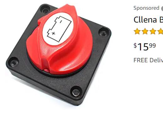
Here's the non-motorized price.
manual_switch_yhr83b.jpg


While OFF and ON would be nice I can live with OFF only. This means a solenoid type action where a PLC generates a brief ON could maybe pull something. Perhaps something like one of these kill switches.

Kill_SW_qf5eko.jpg


Or perhaps twist something like one of these:
Chrome_Disc_SW_mcyixj.jpg


Or pulls open one of these:

KnifeSW_cgvcho.jpg


I could run a motor too.
I have a couple of 3D printers and I'm not afraid to use them :) I can print most any cam, lever, shaft, housing, frame, linkage, or mechanism.

Suggestions?


Keith Cress
kcress -
 
Replies continue below

Recommended for you

Love it Spar! I like that better than the Thing one.

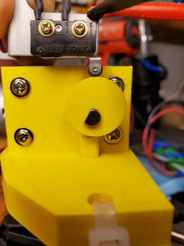
Yes! That is what I need. I need it to self stop once it's cycled. To cause a cycle I short the "stopping" microswitch at the top of the cycle.


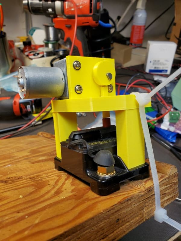
Here's what I've come up with. Note the quality fastener tiewrap. That's what you get when you discover you need 2-3/4" long fasteners at 2AM. The other side is a toggle bolt. Gross!

20200908_004819_oncdnd.jpg


TADA!

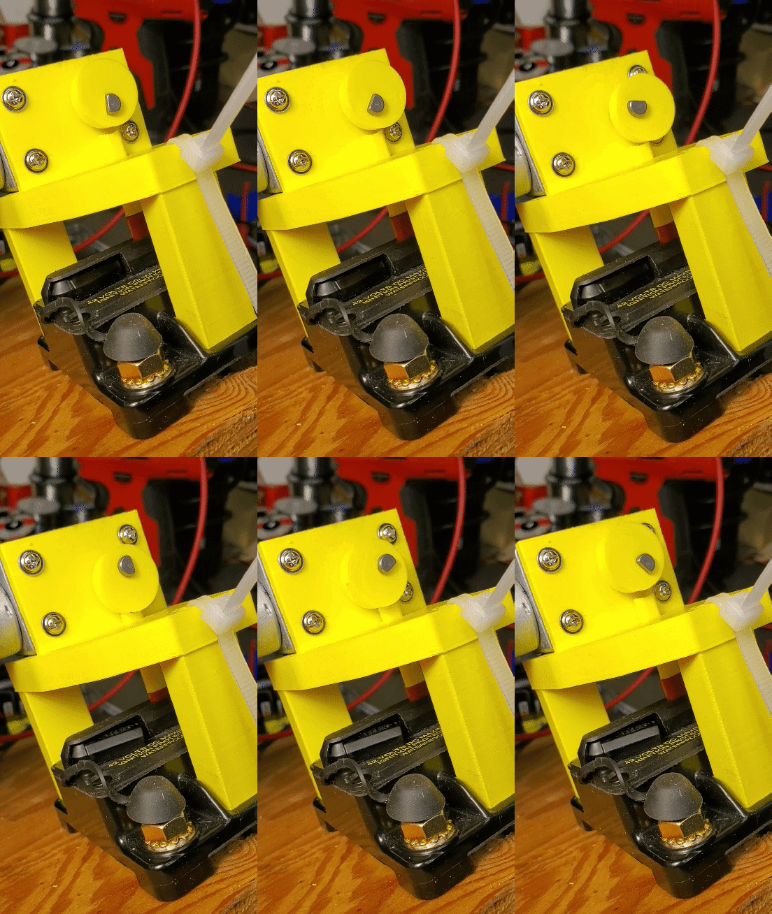
Note: The whole point is to poke the manual trip button on the circuit breaker. Done enough you see the breaker arm swing out.

20200908_005105_1_1_qr0r3u.gif


Next I'll rev it so it has this on it to terminate each cycle.

20200908_014730_siozrw.jpg


Total cost per unit with zero standby current $19. Not counting the, -ahem- cost of BricsCad platinum and its near vertical learning curve.

Keith Cress
kcress -
 
Nice.
I love the box, Spar. I haven't seen one of those for a few decades now.
That's a perfect project for "Make:projects". grin
Bill
--------------------
"Why not the best?"
Jimmy Carter
 
So open is covered. Is closed not needed?

It doesn't appear to fail open as indicated above.
 
stevenal; The black thing is a circuit breaker that will open regardless during a fault. This thing ideally should never need to operate. It's so my PLC based Battery Management System (BMS) can disconnect the battery pack if any single cell gets below a preset voltage limit. All the normally connected systems, like the chargers or inverters, only look at the battery voltage which doesn't speak to the cell voltages. Underdischarging one cell is a disaster so they must be monitored individually. Hence the BMS and hence the need to disconnect elsewhere than the inverters who're just seeing the total battery voltage.

If a disconnect on this system occurs a human needs to intervene and can flip the little lever back in. Closed is not needed.

Keith Cress
kcress -
 
That means my first solution back in June was, IN PRINCIPLE, the solution you chose to go with.
Just all fancy and had to 3D print sumthin.


Spar... I have a 400mm x 400mm x 500mm printer I have to use..

So.

Yes!

BTW I've got the final rev printing so hopefully I can show y'all the end result soon.


Keith Cress
kcress -
 
Sure. Ignition protected for use on gasoline powered water craft as well. Faults are only one type of failure mode. The objection to the latching relay seemed to be that it would not open upon loss of signal from the PLC.
 
Steven; I understood the the objection to latching relays to be the inability of relays to interrupt the DC currents and voltages present.
The objection to latching contactors was the high cost.
Keith wanted to avoid anything that would require a steady current drain.

Bill
--------------------
"Why not the best?"
Jimmy Carter
 
Nit Picking.OK to ignore completely because it works.
Observe the point contact on the pushrod and the offcenter forces.
Consider a convex end rather than a concave end to minimize point contact.
Move the pushrod to or slightly past the center of rotation to minimize side forces.
Or reverse the direction of rotation of the cam.
Or, considering that this may accumulate a dozen operating cycles over its lifetime, and that many only if you get a bad batch of batteries;
Ignore this post and use it as is.
Nice work, Keith.


Bill
--------------------
"Why not the best?"
Jimmy Carter
 
Ha Bill!

Wouldn't using a convex contact point increase the point load forces causing accelerated wear? I thought maximizing the surface contact would reduce wear, but what do I know being a sparky.

I've probably run that thing about 30 cycles already and can't actually see any degradation.

I also think I see a tiny side shift of the 'rod' against the red button.

But your point about a low cycle life is probably a good one unless I attempt to use a battery with a really weak cell that causes daily ejection from the herd. Probably won't do that though I do in fact have a battery with a low capacity cell. A $^@%*!# 185 lb battery with a bad cell.
6bm5afp.gif


Keith Cress
kcress -
 
In your case it is not very important, but the concave is changing the motion profile so that the cam alone is not controlling the motion any longer. A flat top on the cam follower will result in line contact, and allow slight rotation of the follower to get even wear.
 
Hi Keith. Take a close look at your video clip.
You have sharp point contact for almost all of the stroke from the edge of the concave.
You have some full contact at the bottom of the stroke and then some sharp point contact on the upstroke.
The flat surface suggested by Compositepro may be better than the convex that I suggested.
That will give point contact from a curved surface rather than a sharp edge.
That said, that is some nice programing to print that concave end.

Bill
--------------------
"Why not the best?"
Jimmy Carter
 
Interesting stuff Il'l confess I'm having difficulty wrapping my head around. That is the 'point loading' aspects of the various head shapes discussed. Wish I had a graph of position verses pressure or something.

At any rate the red button force goes up linearly with distance being probably 3x harder to push at the bottom. I am pleased to see the most contact surface occurring at the bottom of the press. However I'm surprised to see pretty much only point contact everywhere but at that one point. I was expecting there to be a large contact surface everywhere not at only the bottom.

The cad package allows one surface to shear off another one. Though, that was indeed a painful bit of learning.

Keith Cress
kcress -
 
What you appear to be missing is that the cam eccentricity results in a side-to-side movement as well as up/down. Your follower cannot follow the side-to-side movement, so your cam does not stay seated in the concave that you made.
 
This may work with a previous suggestion that I proposed.
Gang those devices together and use one gear-motor and multiple cams.
Cut your pushrods 1/4" short and use small solenoids to insert spacers so that only the units with the solenoid energized trip the switch.
The feasibility of this approach depends on the relative price of solenoids vs the price of gear motors.

Bill
--------------------
"Why not the best?"
Jimmy Carter
 
Status
Not open for further replies.

Part and Inventory Search

Sponsor