Continue to Site

Eng-Tips is the largest engineering community on the Internet

Intelligent Work Forums for Engineering Professionals

  • Congratulations SDETERS on being selected by the Eng-Tips community for having the most helpful posts in the forums last week. Way to Go!

Maximum possible contact and a single solution

greenimi

Mechanical
Nov 30, 2011
2,382
Per ASME Y14.5-2018
7.12.4 Pattern of Features of Size RMB
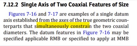
When RMB is applicable in a feature control frame to common datum features of size used to establish a single datum, the true geometric counterpart of each feature shall be fixed in location relative to one another. The true geometric counterparts shall expand or contract simultaneously from their worst-case material boundary to their LMB until the true geometric counterparts make maximum possible contact with the extremities of the datum feature(s). When irregularities on the feature(s) may allow the part to be unstable, a single solution shall be defined to constrain the part.
Questions:
1.) What means maximum possible contact?
2.) What means "single solution" default for unstable/rocking datum features (that replaces the former default of a candidate datum set) ?
 
Replies continue below

Recommended for you

Per ASME Y14.5-2018
7.12.4 Pattern of Features of Size RMB
When RMB is applicable in a feature control frame to common datum features of size used to establish a single datum, the true geometric counterpart of each feature shall be fixed in location relative to one another. The true geometric counterparts shall expand or contract simultaneously from their worst-case material boundary to their LMB until the true geometric counterparts make maximum possible contact with the extremities of the datum feature(s). When irregularities on the feature(s) may allow the part to be unstable, a single solution shall be defined to constrain the part.
Questions:
1.) What means maximum possible contact?
2.) What means "single solution" default for unstable/rocking datum features (that replaces the former default of a candidate datum set) ?
Max. possible contact for RMB is what it sounds like - it's when the datum feature simulators reach the smallest size (for shafts/pins) or largest size (for holes) given the restrictions that act upon them (for example staying coaxial to each other) and stopped by the datum feature itself. It also means it can't stop expanding/contracting until in contact with the datum feature.

As for the single solution, search for "constrained least squares". It was discussed on this forum in the past.
 
Greenimi
do you have access to a mechanical inspection department. go and volunteer.
to get a better grasp. some times a hands on approach really helps.
 
Max. possible contact for RMB is what it sounds like - it's when the datum feature simulators reach the smallest size (for shafts/pins) or largest size (for holes) given the restrictions that act upon them (for example staying coaxial to each other) and stopped by the datum feature itself. It also means it can't stop expanding/contracting until in contact with the datum feature.

As for the single solution, search for "constrained least squares". It was discussed on this forum in the past.
So are the simulators independent from each other?
 
As i stated in the previous thread:

If one simulator stops contracting to get the smallest perfectly formed cylinder circumscribed around the actual "as made" feature, what is going to happen with the other simulator? This second simulator will stop too or will keep contracting?
That was my main question about the interpretation.

Do you have any suggestions on how to interpret (per the standard) this RFS scenario?
Do we need a note to explain to the end users or the standard has already clarified this RFS case?

Or if you have a pattern of two holes modified at RMB in the callout (in the FCF) for other feature, HOW I am going to simulate this hole pattern?
With two expending pins perfectly located and oriented to each other and those pins will expand simultaneously until what?
Here is the unknown:
If one pin stop expanding what is going to happen with the other pin? Will stop expanding too? Will keep going?

The text / verbiage from the 2018, which I copied on the onset of this thread, is not clear, in my opinion, but I might very well be wrong.
Is the math standard of any help? Probably not, because the latest (2019) edition of the math standard has been released to support Y14.5-2009 and NOT Y14.5-2018, hence my dillema is not solved.

Therefore, how do YOU see and solve the issue?
 
greenimi, what implied to you that they are independent from each other?

As I said " datum feature simulators reach the smallest size (for shafts/pins) or largest size (for holes) given the restrictions that act upon them (for example staying coaxial to each other) and stopped by the datum feature itself. "

That is not independent from each other.

The goal is to make them act as equal as possible. While the standard says they "shall expand or contract simultaneously" a theoretically more exact way to achieve that would be to make them contact the datum features simultaneously.

So you are of an opinion that if one datum feature simulator stops expanding or contracting then THE OTHER shall stop expanding or contracting (even the second datum feature simulator did not reach its full potential of maximum possible contact)?

Is my understanding correct?
So basically you put more emphasize on simultaneity and less on the maximum possible contact, right?

I am not saying you are wrong I am just trying to understand it.

I understand that " a single solution shall be defined to constrain the part", but I am not understanding what is the correct way (read standardized way) to get there.
Or maybe even the standard did not clearly stated how............
 
Last edited:
So you are of an opinion that if one datum feature simulator stops expanding or contracting then THE OTHER shall stop expanding or contracting (even the second datum feature simulator did not reach its full potential of maximum possible contact)?

Is my understanding correct?
So basically you put more emphasize on simultaneity and less on the maximum possible contact, right?
No I am not. Where did I say or imply that?
I said " a theoretically more exact way to achieve that would be to make them contact the datum features simultaneously " which cannot lead to such a conclusion.

As for the single solution, did you do the search I suggested?
 
give an actual part or fiquire. you guys are making this way over complicated.

how flat are the parts
how straight
surface finish
how rigit
location datums primary, secondary , and so on
sometime to achieve drawing requirements
surfaces have to be machine to achieve other details. tooling purposes.
but it affects how one inspects a part.
 
No I am not. Where did I say or imply that?
I said " a theoretically more exact way to achieve that would be to make them contact the datum features simultaneously " which cannot lead to such a conclusion.

As for the single solution, did you do the search I suggested?

Yes, I found this thread

It is for the "single solution" and the " "constrained least squares""
Do you see any "other" discussions relevant to this subject?

But my main question stil remains: Is it crystal clear how to simulate a pattern at RMB?
I don't really think so.....
 
Let me ask you a direct question:
Per 2018 the default stabilization procedure has been changed from candidate datum set to a single solution that minimizes the separation between the features and the TGC.
Is this new procedure more clear than the old one regarding the pattern feature at RMB?
If yes, how?

7.11.2 Irregularities on DatumFeatures Applicable RMB
If irregularities on a datum feature are such that the part is unstable (i.e., it rocks) when it is brought into contact with the corresponding true geometric counterpart, the default requirement is that the part be adjusted to a single solution that minimizes the separation between the feature and the true geometric counterpart per ASME Y14.5.1M. If a different procedure is desired (candidate datum set, Chebychev, least squares, translational least squares, etc.), it shall be specified.
 
Last edited:

Part and Inventory Search

Sponsor