Eng-Tips is the largest engineering community on the Internet

Intelligent Work Forums for Engineering Professionals

Mexico City subway overpass collapses, killing at least 23 and injuring dozens 2

Status
Not open for further replies.
Replies continue below

Recommended for you

This forum was my first stop for information (after news articles). I watched the security camera video a number of times. My first fleeting impression is that the failure occurred at mid-span of a simply supported beam, rather than at the end connections. I'll be interested in following this thread.

Edit to add: I found the best copy of the security cam video of the collapse on Twitter, from Voice of America, No distractions of news heads, just the security cam.
 
Based on the poor video of the collapse it looks to me that the overpass failed mid span rather than falling off a column, the spalling on the underside of the span seems to be close to where it failed.

image_gqukfb.png
 
Good spot.

Right where that beam connects in at mid span - Is that a crack in the flange?

Picture from one side

image_a7mrc6.png


Picture from the other side

image_nmxcuk.png


That connection does look more than a little odd.

Looking at other joints it seems there is a construction weld in the middle of the span.

Something failed hideously fast though.


Remember - More details = better answers
Also: If you get a response it's polite to respond to it.
 
I would have guessed that the tracks were on top of the beams, but it appears from the overhead news picture that there are 2 sets of tracks where there are 2 beams so the tracks must straddle the beams. The third beam starting to split off to the right is for the start of a 3rd set of tracks.

I count at least 5 welds in each bottom flange on each beam in the section that failed. So, that's a welded construction beam. Is the flange in that type of construction commonly made from pieces butt welded together? I would have expected the flanges to be continuous pieces.

Is it also possible the train punched through the deck and that shock loaded the beams enough they failed. Maybe it de-railed? In the news picture the right end of the train looks to be about a 1/2 car width out of line with the track.
 
Maybe it is just my eyes, but the top flanges of those beams appears to be not as wide as the bottom flanges. That would only be logical if the beams are composite with the deck. But the deck sections appear to be precast, so how does that work?
 
From the photos the train appears centred over this girder:

BA5301F7-605E-455E-A768-B84E99BB48CA_dz0tzk.jpg


This is roughly midspan. There is a large crack opened up joint in the deck, and associated corrosion, and a fairly prominent bottom flange splice in the same location. You can see pits etc in the weld.

FA0F71FF-1643-453D-81D5-003CA600D1CC_mxivyo.png


AF95D2E2-69B5-4E34-9453-DC8A55DB6A81_g7rv5h.png


If deck joints are cracking, and rusty, the beam may have been working harder.
 
Speculation. Comments and contradictions welcome.
1. The train jumped the tracks.
2. The train broke through the rotten concrete.
3. The train broke the beam butt welds on the way down.


Bill
--------------------
Ohm's law
Not just a good idea;
It's the LAW!
 
The failure was sudden, so definitely it was fatigue cracking of the butt weld across the bottom flange - category E' by AASHTO ( 2.5 ksi constant amplitude fatigue threshold). Anyway, although shop welding of the elements of the railway bridge is permitted in controlled environment and with the welds checked with X-ray, this was definitely not the case, as the welds looks bad, and were likely done in the field, which is strictly forbidden by the AREMA. If the rest of this elevated structure was done the same way more such tragic accidents are to be expected.
 
you beat me to the punch wiktor. I agree with your assessment; my gut feeling after seeing the photos was fatigue. In the photo from Tomfh, there appears to be a floorbeam at midspan but the there's a large gap on the web between the bottom of the connection plate and the bottom flange; not a good detail. I would be interested to know the fracture toughness of the steel; may have played a factor as well.
 
That 'crack' in the deck is actually a joint between two precast deck planks. I agree that the butt welds look rough, but doubt they were made in the field.

Any ideas as to why the top flange is smaller than the bottom?
 
The shop welds in a railway bridge shall be grinded smooth and x-rayed - so much for good workmanship. Any irregularity in the tension elements acts as a stress riser
The smaller top flange was due to assumed composite action of precasted deck. With the deteriorated joint that was not the case, and increased stresses in the critical section.
 
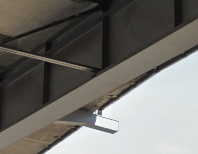
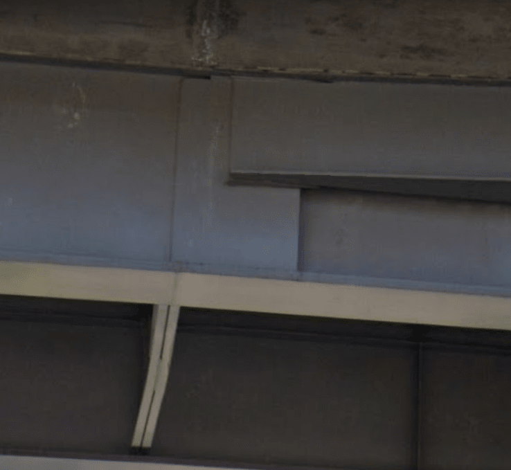
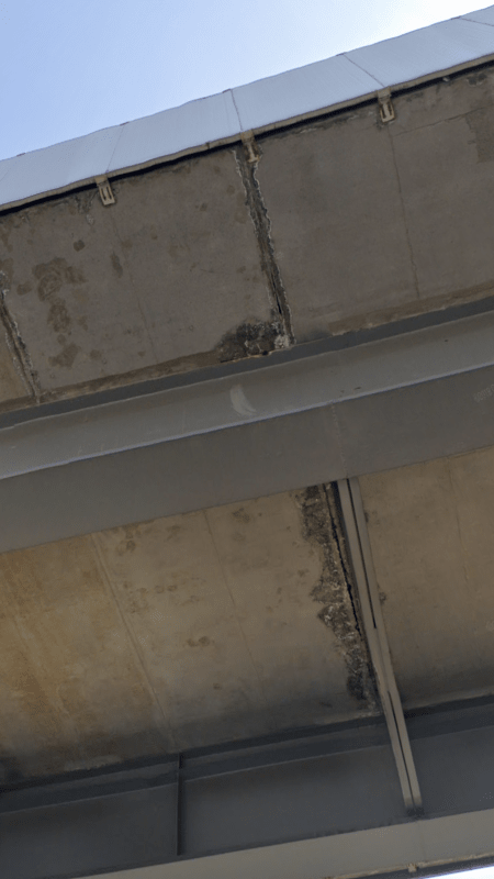
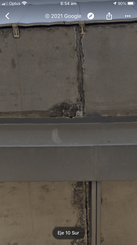
I agree that there was poor workmanship in the welds. That is not surprising in Mexico, but still doubt the welds were made in the field.

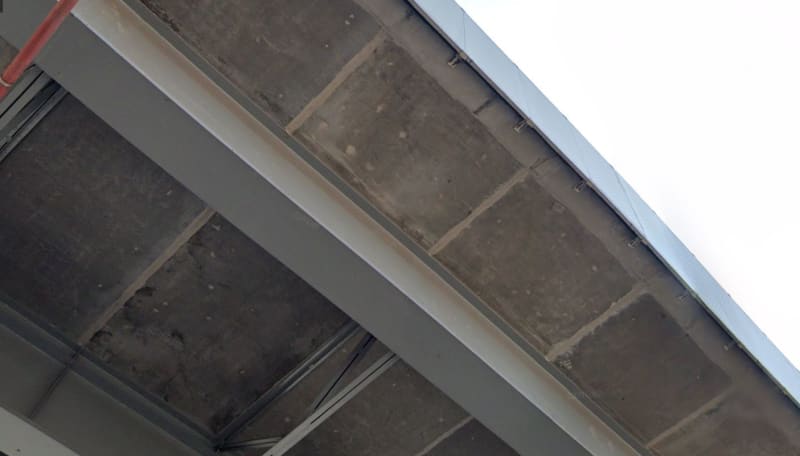
As to composite action, I suggested that above as the reason for the smaller top flange. But if that was assumed, how could it have actually been accomplished, with those precast deck sections? If there was not actually composite action, the top flange may have failed before the butt welds in the bottom flange. Anybody have photos of that failed area?

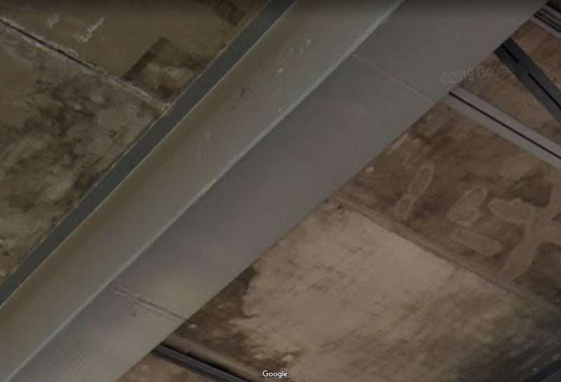
Just supposition, but perhaps the deck was to be cast in place, but the contractor decided to use precast, without anyone giving due consideration to the implications.

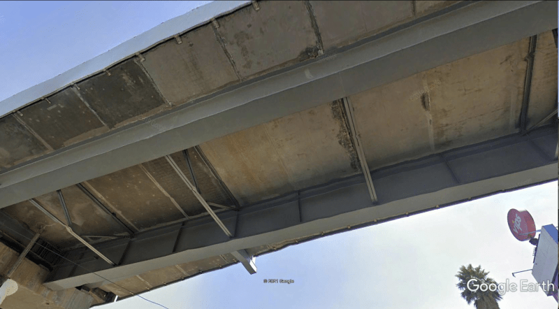
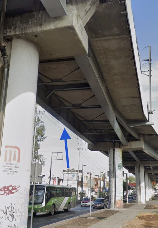
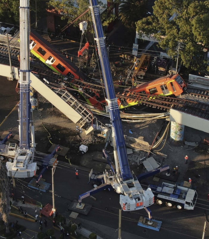
The articles said this was a "subway overpass collapse", so actually part of the Metro system, with this part being overhead trestle. Not sure how extensive the overhead part is, but the entire bridge system needs a rethink now.
 
The composite action of precast decks is actually quite simple - holes in the precast planks where the shear studs are located, filled with HS grout. The quality of the fill in between planks is critical, as these shall be done extremely well. To avoid locking DL in the steel the span shall be uplifted during installation of the planks.
I did not notice initially the big difference in flange sizes which could be critical, as the local buckling of the top flange could lead to lost of plane bending. The diaphragms holding the bottom flanges doesn't look too strong, and the one just below the crack appears slightly bowing. So, it would be either fatigue crack at the tension flange, or buckling of the entire beam.
 
Status
Not open for further replies.
Back
Top