Eng-Tips is the largest engineering community on the Internet

Intelligent Work Forums for Engineering Professionals

Miami Beach, Champlain Towers South apartment building collapse, Part 07 90

Status
Not open for further replies.
Replies continue below

Recommended for you

rodface said:
This one in particular was closest to the edge of the still-standing portion and can be seen to be clearly on the overhang from other angles (Can't find a good picture at the moment)
Roof anchors. Again. Notice it’s not any closer to the edge than the humongous communications array (I presume) with its massive wind loading (which is obvious).

C3185ED8-CEA6-449C-9166-42D284D6DA1D_mdopnw.png


That installation (it’s the thing to the lower-right that’s as big as the circle around the anchor you drew) didn’t bring the building down. But somehow a little bit of hammer drilling into a thousands of tons structure somehow vibrates the pool slab free 12 stories below or otherwise snapped a parapet off? That dog just don’t hunt.

People are so fixated on things they can’t see the forest for the trees. Now we are squinting at two different pictures to make them 3D? Woof!
 
The roof anchors are a non-issue here. They're used for fall-protection tie-offs. If some hammer drilling and Hilti's are compromising the structural integrity of a roof, you have way way bigger problems going on here. They're a moot point... so why even bother discussing it?

If the parapet above the collapsed pool deck did fall, it's mostly made of CMU (or cinder blocks). Once that hits the ground, it's going to shatter like glass. *IF* that did happen, for that to bring down a structural slab points to structural issues (weakened concrete / compromised rebar) on the pool deck as pointed out in the 2018 report. The cantilevered roof overhangs and balconies are part of the roof / floors and tied in to the structure with rebar. If those were to fail, they wouldn't just drop away from the building cleanly unless you cut all the rebar at once and sawed them off. It's a proven construction method as indicated by any Frank Lloyd Wright or brutalist architecture style building. I don't see that being a primary cause either.

I do find it remarkable that a failed slab or column took down such a large portion of the building. We've all seen the CDI building demo videos where they're putting explosives in just about every column in the first 2-3 floors of a building along with other methods to weaken the structure prior to detonation to bring it down on itself. This building fell right in it's own footprint without any such assistance. Was the concrete too weak? Did they not use enough rebar or the right thickness of rebar? Was the rebar completely rusted away?

Compare this to the 1995 bombing of the Murrah Federal Building in Oklahoma City. Some similarities here... reinforced concrete slab and column construction. The bombing took out 4 columns but most of the building remained standing.


Like with any major accident / disaster - there is no singular cause. A series of events over the years led up to this collapse.
 
ThtI2Q5_d_2_tqd1ki.jpg


I find it odd that beams 33,34 and 35 appear to be exactly in place. They also appear completely intact. Does this mean the columns below (N8,O8, N9.1 and O9.1) did not fail?
 
Can anyone please advise me as to where can I see the reinforcing for the beams selected? I see this as a critical area. Also a dimensioned drawing -Plan?
Thanks,
BEAM_SHEAR_dzsqog.jpg
 
sgw1009 (Computer) said:
In order... to obtain a 3D image

That's the best sense of what is or isn't in there I have seen. I think it adds slightly more than just depth perception. But now I am permanently cross-eyed. I have the sense that the piece laying cross-wise that is dark may actually be the missing column as though a partial length of it is still white but another part has had the exterior crumble or shatter to expose the core thus it is darker.

Edit: after refining my cross-eyed stare, the dark portion is a little too dark to be concrete..... unless somehow it got tar all over it. I mean it's not like thing beside it is a tar buggy or anything like that.

Edit2: The other things that the double vision overlay does is provide noise reduction and dithering. It dithers the width of the gate bars so they seem thinner and block less (you see around them a bit). Noise reduction occurs by emphasizing what is there and de-emphasizing what it not. The added benefit is you get depth perception.
 
Vance,

That model is not accurate where you have the patio slabs. The beam along column line 9.1 is just the slab step and wouldn't look like that at the patio to living floor step since it is only a 7" step.
 
Optical98 (Computer)20 Jul 21 22:58 said:
Can someone explain what the black circles and blue dots represent?
The "blue dots" are symbols from the legend. They are probably entries in the source document for this map. The black circles, some with slashes through them or text are whatever the briefer said they were. What's more interesting is probably the shadows of the columns...

SF Charlie
Eng-Tips.com Forum Policies
 
spinspecdrt said:
I find it odd that beams 33,34 and 35 appear to be exactly in place. They also appear completely intact.

lol. Like with many, many photo analyses on these threads, I have to wonder: how can you possibly see that?

This image is 640x412, and rife with jpeg artifacts. I can only tell that some sort of something was at each column location. The state of the column and how intact it is? No way. Maybe you're looking at a high-res view or something?
 
From the photos of the garage provided by a prospective buyer, Beam A at column Line M is dropped below the slab and not integral to the slab as detailed above. I believe these beams may not have been constructed as part of the slab and may not have been supported in directed bearing on the columns. I believe they may have been hanging off the horizontal reinforcing. That also explains the intact “frame” mentioned above by Spinspecdrt. 3DSoftwareDev, I think the resolution is clear enough to see that something different is going on with these beams. I see these intact beams as some evidence that the plans and the construction of the transfer beams is not consistent or there would be slab attached to these beams.

 
rodface said:
Something that continues to bother me about these roof anchors (as a total layman):

Some anchors are installed atop columns. But others are installed on the overhang.

Why not have anchors only over columns to ensure that the roof overhangs are not compromised in any way? Even as a layman it occurs to me that it is a bad idea to cut/drill/add weight onto a cantilevered structure. Of course if it is on the plans I would assume that the engineer had considered this...

Probably wouldn’t be a bad idea to understand how suspended scaffolding is arranged before questioning the anchor positions.

As a layout example:

7C9AA8AA-3771-4AF1-AFBE-57ED4B8EE748_ieisfm.jpg


And load test example:

6B0144CC-17E7-4B47-8CF5-A2D79963DFF5_hsmjxl.jpg
 
Thermopile said:
The point of my posts is to generate out of box thinking, as I feel that is what it takes to solve this riddle. IMO it is a system of many parameters that led to the structure giving way to gravity.

As a child I built many things with erector sets, and this may not be a Spartan5 level analogy, but I think the tight original design wing-nuts will see this more from a by the book perspective, where as the loose wing-nuts will look outside the box at the warning signs that may have been overlooked because our Special Inspector Training is NOT GOOD ENOUGH yet to solve this unfolding new riddle.

This was a system of failures from original design to lack of well baby care that led to this collapse. Why did they not start working on ground level first, it was because Association would not allow pool out of service nor possibly loss of parking spots, so they started on roof of a time bomb.

I know when my wing-nuts were loose at the joints of my erector set vs tight joints, the load capacity and stability of the structure varied greatly. Now this was a young child figuring this out.

Loose joints probably were one of the biggest issues in this building, leading to racking of structure, thus shifting load paths over time and shifting stresses. Think about removing masonry in fill non load bearing partitions that may have been proving some racking support.

It appears column cold joints between floors were not well tied together. Slab deflections will put lateral stresses on the column to slab joints and could put the columns in towards the middle of some units, while pulling them away from slab to column joints in adjacent units.

Why can't some folks see this concept???

I would argue it takes a far different skill set to design a structure from scratch, with the Architect dictating a lot of problems for the structural engineer to figure out solutions too, that go against anything the EOR wants to do, but hey what happens if Architect and customer unhappy with EOR..... They find another EOR that will do what they want.....

Folks are ignoring the loose joints of this building, and the effects of vibrations of varying degrees on those loose joints, yet the joints are the most critical part of the design process.

Look at Hard Rock Collapse in NOLA. Did not the steel erectors leave out bolts at connections and leave the joints loose as they added floors above, coupled with design issues.

Loose joints whether steel or concrete can become a big issue.

So if you read this to this point, you realize I am a loose wing-nut.... I did the opposite of Demented and went from Structural start to Aerospace. Think about it, Aerospace engineers design stuff to blow up or exploit what Structural Engineers Design......

And AeroSpace Engineers do all this without a PE Stamp and the liability that comes from doing Public Structures....

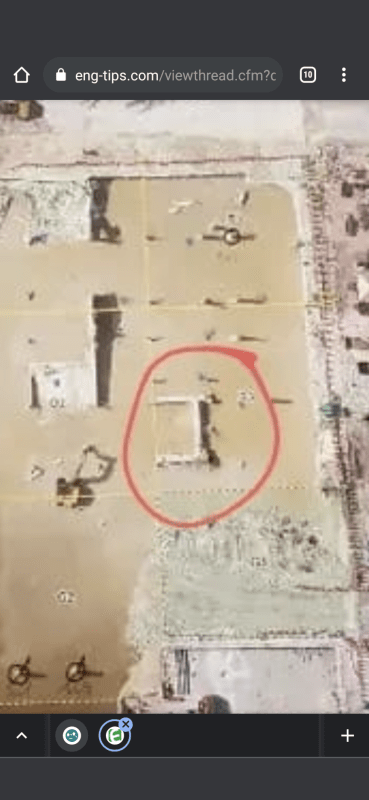
The shaking of Champlain Towers appears to have started being noticed when the stimulus of pile driving started next door. Does that mean the pile driving caused the collapse. NO. But it may have been a key contributing factor to a exponentially decaying defective structure. And this construction happened after the 2018 Morabito Report.

What I really don't understand is why so many tight ass wind-nuts are taking such a hard stance that only a simple solution and only their theory could be possible.

You can not pick and choose which pieces of evidence you consider. It is all important, and must be considered and factored into the algorithm....... And that algorithm may not be a simple linear equation......

PS I typed this on the fly, and did not proof read, so there may be typos....

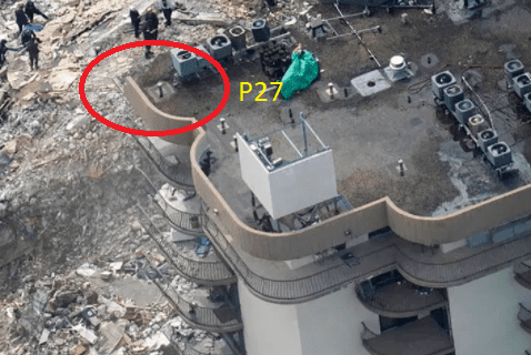
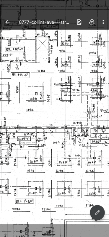
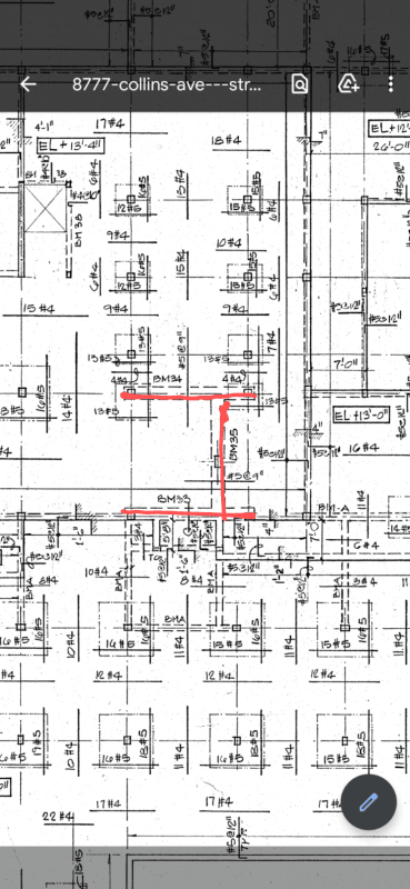
Think about it. I, K, L, M 9.1 Column line had cantilevered slabs to transport moisture into the exterior column line to slab joints at each floor column joint. Was the cantilever slabs well maintained to prevent moisture intrusion in this area? I think no, these were neglected just like the garage slab at wall interface. We can see the water soaking into the building in the garage tour. Water intrusion is not stopping at the exterior wall...

Edit for Spartan5. Dirac Live does a great job eliminating those room modes you are referring.

This is take 2. Hopefully my rambling thoughts make sense, I had just lost an hours worth of typing after a long day.

I enjoy being a loose wing nut. It's helped me achieve some things that I am quite proud of. Although life took me away from finishing my degrees, I never stopped engineering. Thankfully the aerospace industry is what it is. I would rather put my name on any print or fabrication piece in the aerospace field than be responsible for anything done in the South Florida structural, specifically ocean front, field.

Why can't people see the concept? *shrugs* One day people will learn to use both eyes. I doubt my own ideas more than anything else which is why I'm trying so hard to find evidence of anything else. All the odd stuff that makes little sense. There's just so much wrong here. So much wrong.

Up until recently I was under the impression that the building stood on 42" and 48" precast 14"x14" columns. I was unaware of the drawing revisions that specify Franki piles. Still haven't seen it, but I am not saying it doesn't exist. The version of drawings I have, dated with 1-17-80 revisions and notes, calls for only the following columns to sit atop PIF (I may be wrong on some of these because of the .1 denotations)
B1.1, D1.1, D2.1, D5, D8.1, D11, And the entire 1.1 columns row.

The remaining columns were to sit upon 42" and 48" precast 14"X14" driven piles. Floating in the sand, where fucking boats used to flow through!

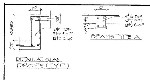
I know it seems stupid. No one would ever actually go ahead with possible building something like that. But then again, no one would ever omit a large portion of steel reinforcement...

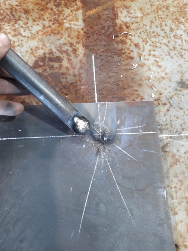
I have seen some shit go on here. You guys ever catch a shop welding nelson studs to unprepped steel for embed plates, but blasting it with aluminum filler and hoping the hot dip galv and going in the concrete before the inspector gets there gets it to pass inspection? Not saying everything in Miami is suspect, but Miami we cannot blindly assume the building is built as intended.
20200723_130203_ri9wyw.jpg


Treat the piles as suspect. The additional weight of those pavers, the tile, the windows, the cars, the rain, etc, all really starts to look like scary numbers added on top of the existing building. Subsiding in key locations that are slightly quickened due to heavy loading, could cause portions of the building to sink slightly more, and at an unusual way, compared to the more secure areas. Cause of the collapse? Probably not. But a very valid point, and one that could also affect other buildings.

Another thing we need to remember, is there was a beach restoration project done in surfside. The beach that we see there now was trucked in because it damn near all eroded away. Water may have found a way past the bulkhead. The pile driving from next door definitely didn't help the settlement of loose beach sand either. Even if they were all Franki piles, this building was not set on any solid rock surface. Where is the logic here?


Precision guess work based on information provided by those of questionable knowledge
 
3DSoftwareDev, I can clearly see the beams. No squinting, enhancement or imagination required. It's the only location in the building this arrangement of beams occurs. Obviously from the picture you can't tell the condition of the columns.
Screenshot_20210720-192239_ovjckv.png


Screenshot_20210720-192204_xwdbsk.png
 
spinspecdrt said:
3DSoftwareDev, I can clearly see the beams. No squinting, enhancement or imagination required. It's the only location in the building this arrangement of beams occurs.

My apologies, I read "beams" and thought "columns" because at some point previously in these threads, someone conflated the two and now I'm screwed up. [glasses]

Yes, that beam assembly is certainly more clear than whatever remains of the columns. It was discussed previously; there are some decent close-up shots of it in previous pages I think. Seems to be intentionally kept intact by the on-site crew.
 
An interesting note is, of the 80 units that collapsed, 34 of them were empty (36 if you count 611 and 111 that escaped). I've not researched the later demoed units.
 
Status
Not open for further replies.
Back
Top