Eng-Tips is the largest engineering community on the Internet

Intelligent Work Forums for Engineering Professionals

Miami Beach, Champlain Towers South apartment building collapse, Part 11 54

Replies continue below

Recommended for you

SFCharlie said:
Is that a compressor between the carbs and the engine compartment??? Looks more like todays electric motors only much larger?

It's a Roots-type supercharger--intertwined rotating dual lobes--sorta like gears. A nice thing about them is that there's no turbo lag.


spsalso
 
That's a roots blower from EMD engine. These engines have a blower for each bank. The most powerful roots blown engine was 2200 horsepower so the pictures engine would support 1100 horsepower which is quite reasonable from a big block. Just don't rev it beyond 900 rpm.
 
Detroit Diesel used that type of blower to scavenge the exhaust gasses from the 71-series 2-cycle engines.
There was a 2-71 Blower, a 3-71, a 4-71, a 6-71 and an 8-71. The 6-71 was the most widely available model and was used on many high performance cars. To serve the market for a larger displacement blower, after market shops developed a model 10-71 blower, but GM never made a 10-71 engine. The 10-71 was after market for high performance engines only.
edit. Now available for racing are 14-71, 16-71 and 18-71 blowers. These were never used on Detroit Diesel engines. The 12-71 engine used two 6-71 blowers and the 16-71 engine used two 8-71 blowers.
Roots type blowers were also manufactured in other displacements for industrial use.
After WW2 there were thousands of military surplus 71 series engines on the market, a large number were 6-71s from landing craft.
Surplus 6-71 blowers were cheap and plentiful and much sought after by performance builders.

--------------------
Ohm's law
Not just a good idea;
It's the LAW!
 
Just remember that the 71 indicates the displacement per cylinder. These were some of the first modular engines. Shortly after, Kettering spearheaded the development of a medium speed engine for EMD that was 567 cubic inches per cylinder and eventually evolved in to 645 and 710 cubic inch per cylinder models.
 
All About Money said:
When Demented was looking thru all the maintenance and repairs, one was the tear out of the pool gutter system and installing a new gutter system which appeared to be higher in elevation than the original one. I think when the raised the perimeter of the pool and hot tub, they added probably more sand to raise the patio tiles to match the elevation of the pool and tapered the deck from new pool curb height into the rest of the patio deck. I know in some pictures I have seen, way back in this long thread, it looked clearly like the area around the pool and hot tub was higher elevation, and tapered back into the rest of the paver level on patio deck side of the pool.

I don't think what you are seeing is structural deformations below.

Perhaps Demented has the info handy to confirm my memory?
Correct. That section of slab was original height. Barely any sand was used there to match the pavers. The surrounding areas were raised. Around the exterior of the main building, it was the same. A slow taper that allowed water to collect and pool at the border of the building/deck.

Don't have it handy, but I can dig through the stuff later. However, I did find a series of failed inspections on the rebar placement at that location but it was subsequently approved based on yet another letter from a PE. Same PE and construction firms involved in the other work. Still trying to get as-builts, but those don't exist per the town. I've kinda given up as I've exhausted everything I can dig through being a nobody.

Between the walls falling over in hurricanes, rebar added to an existing design, rebar removed from an existing design, additional sand/paver weight, delaminated slab, epoxy repairs and mortar patching, and pile driving next to that location, I think it's a good location to investigate.

After reading through everything I have, to me it looks like the pool deck restoration work was never finished during a dispute and the pool resurfacing work continued as planned. A 3rd contractor had to come out to fix loose tiles left all over after the hot tub work before the final approval was given by the inspector. Hurricane damage repair work at it's finest.

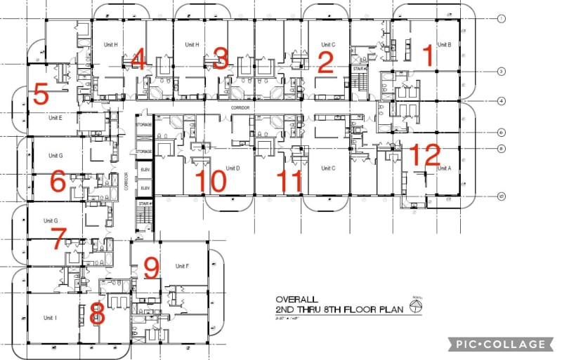
Planters used to be here too

IEGeezer said:
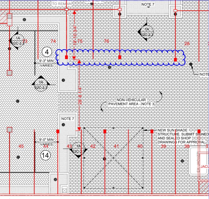
That would be about 45 inches tall. Where did you get that the big planters were 4 ft by 8 ft. In this picture, they look roughly square as they do in the Morabito Consultants drawing I referenced.
4x8 is just the ref name of them I have seen called out on original drawings and contractor plans. There is a slight chance 1 planter, though I am not sure which one, was built by placing CMU bricks along the perimeter of the existing and the original was demod internally and used as fill. This was around the same time they were modified to 45" tall, which was to replace tapered cracked cast concrete caps.

Also waterproofing was there. Just poorly done and trapped water instead. I'd have to dig up the spec sheets again but we've got the weights there.
I don't think geofoam was used either. I've found 0 mention of it in any of the repairs/rebuilds. Rootballs of old palms and seagrapes were likely left in.

The additional sand and raised/clogged drains on the deck was also a massive area for water to pool up beneath the pavers.


This building took quite some damage from a few hurricanes it seems. Has anyone run a simulation on hurricane windloads of this building?
Lets all do the twist!


Disclaimer:
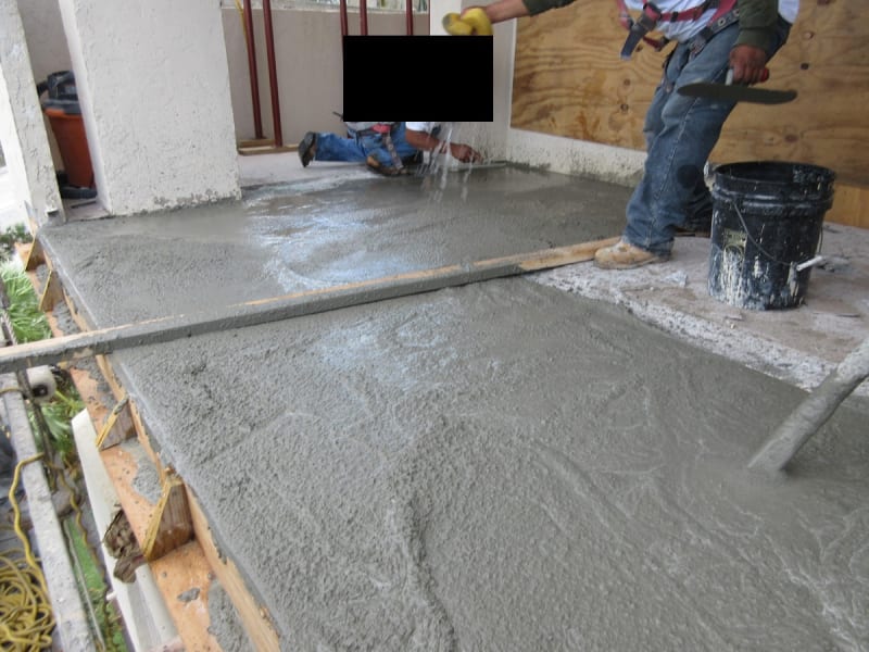
This is NOT a photo of champlain towers south. I'm still told photos of the work there no longer exist. This is partially the same crew that did the work on CTS's balcony, deck, and beam repair. Concrete lab tests were also not done it seems and most concrete was mixed/pumped on site with bagged cement. Processes and work habits typically don't change job to job, especially when the PE and contractor have a relationship.
Concrete experts, does this look right at all? Looks a wee bit wet to me.
doesthislookright_zvkxuh.jpg
 
Demented (Industrial)23 Aug 21 09:37 said:
Concrete experts, does this look right at all? Looks a wee bit wet to me.

It appears no vibration needed with that mix, all the aggregate has fallen to bottom with only watery cream 'floating' to the top?

Assuming there is aggregate in that mix?

Re-defines Layered Pour?

SFCharlie, I am guessing the dog balancing spinning 'Flat' plates with the pencil columns was on the Ed Sullivan Show, as I seemed to remember that act?
 

Detroit diesel also made a Series 53, Series 92 and Series 149 in their blown diesel engine series. One of our farm tractors had a 4-53 diesel that you could hear from 2 miles away. These were two cycle engines and were made in 3-53, 4-53, 6-53, 8-53 and 12-53 engines with 53 cubic inches per cylinder.
 

Buildings do shake in general when there is a construction going on at a site nearby. Currently I am living in an apartment right next to a construction site so there were periods of intense shaking, but that doesn't not affect a building's performance significantly because the buildings are design to handle significant amount of lateral loads. Either wind / seismic. The vibrations though as experienced by occupants must be high accelerations (occupants can feel anything over 10 milli gs as lateral acceleration) and anything over 2.5%g as vertical accelerations, so any acceleration vertically higher than this will lead to some magnitude of occupant discomfort and people can start complaining. But the building deformation corresponding to these accelerations is very minimal. If the vibrations because of construction site work are significant then you may face some significant damages structurally. And if that happens, then we should also see some non structural damages like ceiling plaster peel off, partition wall hairline cracks and so on. Also the construction was happening 3-4 years ago, so if this were the case, then they wouldn't have to repair the pool deck prior to the construction that was going on.

Pool_Deck_Slab_Column_Marks_jrfm39.jpg


Flexural induced punching failure is also a result of lack of flexural / top and bottom steel reinforcement in the slab. When the deck failed in punching, then initially it just feels as if it failed in pure punching shear and yes it was overstressed from a pure punching shear standpoint, but again it is based on the specified concrete capacity on plans. The punching shear stresses at these slabs is a result of two different components, one is pure gravity shear reaction at the column and other is the moments absorbed by the columns below. So the column at Grid KLM/13 were seeing the maximum stress because of these two different actions. Now the demands (just the weight of deck, pavers and sand) were over by a factor of 30% compared to the "Code calculated capacity". This code calculated capacity is also relatively conservative so that we can account for some construction differences, uncertainty in material strength and so on. So if I remove the factor of safety then the Demand to capacity ratio (DCR) 1.0 and on top of it, this is the peak stresses at the slab column joint when I combine flexural plus pure shear stress. Code doesn't allow a redistribution of these stresses as the redistribution of stress depends on what is the contribution of shear stress at slab column joint because of flexural transfer.
Punching_pmgo34.jpg

RAM_punching_failures_hxpiwf.jpg

So we know that the capacity of slab punching realistically was okay to handle the daily load if there were enough flexural reinforcement (The reinforcement that is required for the slab to span between columns). If there is not enough top and bottom reinforcement (reinforcement along top / bottom face of slab) in the slab, then it will lead to moment redistribution. Code allows up to 10% of moment redistribution. What do I mean by this?
Moment_Redistribution_o2hk0m.jpg


Now the slab span between grid K/13 and M/14.1 was 28.5' and the bottom reinforcement was not enough to handle the loads so it redistributes the stresses to the top reinforcement at column. And in general it is okay as reinforced concrete is good at that. But in this case, the top reinforcement at column was also barely enough to handle the loads even without this redistributed moments. So this leads to cracking / significant cracking at the slab column connection face. The magnitude of these cracks depends on the actual daily load carrying capacity and not just code calculated. So this flexural cracking because of lack of top reinforcement and its concentrated placement at top of column lead to a compromise in the punching shear capacity of slab. The top reinforcement was also compromised because of failed water proofing and as the cracks stay open for longer, the rebar corrosion also gets accelerated because rebar corrosion is also a time dependent factor. And since the slab was cracking significantly under its own weight, the crack duration can be justified as (almost) the age of the building.

The rebar corrosion leads to reinforcement delamination effects (not the same as coring because while coring concrete can get damaged in the core sample and does often separate from rebar if core is not big enough). With this delamination effects, you get further reduction in punching shear capacity. So, it was the lack of top flexural reinforcement coupled with high unbalanced moments at these column bays that has lead to a flexural crack at the slab column joint which in turn lead to a punching shear failure because the concrete lost its aggregate interlocking capacity and there by the strutting force. This can explain why the pool deck collapse and why it did take as long as 40 years.
 
Btw unbalanced moments are significant on columns that are supporting different length of slab bays. So in the image above, the slab span adjacent to the circled columns are 20' and 30'. This difference creates a significant moment transfer to the column below and a part of this moment transfer (around 40%) leads to additional shear stresses. So this bay seems to be the most critical bay that could very well have collapsed prior to anything else on pool deck.
 
StructuralMadness (Structural)23 Aug 21 16:58 said:
By the way I finally figured out where to paste text into who you quote. Look for flashing cursor between outsides of square brackets to paste text in between

Thank You StructuralMadness for you excellent explanation. I think I understand most of what you said, or at least got the big picture? [thumbsup2]

I think it was IEGeezer a ways back in forum that mentioned this area was the area he felt was the most overstressed.

Edit: I assume the flexure in this area is due to auto traffic creating unbalanced moments, and then the rectangular columns to boot?

 
StructuralMadness said:
So this bay seems to be the most critical bay that could very well have collapsed prior to anything else on pool deck.

Thank you very much for your detailed explanation. Because I am an analyst rather than an engineer, would you kindly clarify the boundaries of “this bay” as it relates to the space numbers and driving lanes in the garage?

The reason I am asking is because I have long wondered how Nicolas Vazquez and Gimena Accardi, who parked in the garage and got onto the elevator just as the deck collapsed at 1:15 AM, could have missed seeing the first slab that collapsed at 1:10 AM. Of course it depends in part on where they parked and the route they walked to the elevator. But if “this bay” was over a driving lane they didn’t drive on to get to their parking space, or over parking spaces off to the side of their field of vision, they could easily have failed to notice any broken concrete.

Thank you!
 
MaudSTL (Computer)23 Aug 21 21:11 said:
would you kindly clarify the boundaries of “this bay” as it relates to the space numbers and driving lanes in the garage?
2StructuralMadness (Structural)23 Aug 21 16:58 said:
Now the slab span between grid K/13 and M/14.1 was 28.5' and the bottom reinforcement was not enough to handle the loads so it redistributes the stresses to the top reinforcement at column.
+
first where is K/13 and M/14.1
Overheads_of_debris_pile_at_end_of_ramp__zoom_with_slide_in_lower_RH_corner_-_6.1_wwjdmb.jpg

and from StructuralMadness's image, what are the numbers
Overheads_of_debris_pile_at_end_of_ramp__zoom_with_slide_in_lower_RH_corner_-_6.2_cy17jn.jpg

If I have misunderstood any of this, please correct me


SF Charlie
Eng-Tips.com Forum Policies
 

Thanks for checking my understanding. That was close to how I interpreted it too, thinking that a bay was bounded by four columns instead of six. Depending on where the Vazquezes parked, they could have missed seeing it.
 
I found an error in my spreadsheet calculating the weight of the planters. I am also correcting the height of planter #5A from 2 ft to 6 inches. That reduces the weight of the planters somewhat.

Corrected_Weight_of_Planters_with_geofoam_dj0sxb.png


I am also proposing a cause of the failure of column K13.1 and therefore of the building. I am proposing fatigue failure due to the cyclical loads of the parking deck. Although the amplitude of the cyclical loads is small compared to the dead weight of the deck and planters, that may be enough to cause fatigue failure of column K13.1 because the column had a high load. Over 40 years there may have been hundreds of thousands of cycles as I believe this was the valet and visitor parking area. We cannot also forget Building Integrity's point about the deletion of a key beam that would have helped column K13.1.

I would have liked the cyclical loads to be larger to invoke fatigue failure, but fatigue failure checks the following points:

1. It would explain why the structure stood for 40 years and then, seemingly suddenly, collapsed.
2. It would explain the lack of a trigger.
3. It may explain the noises in the building as column K13.1 suffered slow-motion punching shear.
4. Other causes of failure seem less and less likely.
5. Only columns K11.1, K13.1 and K15 would seem to be subject to enough cyclical loads to suspect fatigue failure. Other columns may also have had high loads, but not subject to cyclical loads. The 24 in by 24 in columns may have been stout enough not to suffer this kind of failure.
6. I can't think of anything else. ;)
 
Status
Not open for further replies.
Back
Top