Continue to Site

Eng-Tips is the largest engineering community on the Internet

Intelligent Work Forums for Engineering Professionals

  • Congratulations waross on being selected by the Eng-Tips community for having the most helpful posts in the forums last week. Way to Go!

Miami Beach, Champlain Towers South apartment building collapse, Part 11 54

Replies continue below

Recommended for you

Nukeman948 said:
Maybe they did, weren't they planning to redo this area as part of the pool deck repairs?
It’s not to say that they aren’t there, but I don’t recall seeing the proposed installation of transfer beams or other modifications that mitigated the potential for punching sheer at the pencil thing columns.
 
Spartan5 - they're not there. The morabito plans only called for removing the topping at the pool deck, repairing whatever cracks they find, and then installing a new topping (and waterproofing). They called for some more significant structural alternations along the driveways into the at grade parking.
 
Interesting presentation. Thanks for posting.
If we the "axial compression force ratio" is correctly determined and presented it seems to mirrors the initial collapse quite well.
Same caveat, we can see that the Penthouse addition was not the whole and complete cause.
A "load Ratio" of 1.89 has probably [1 floor added/13 floors total] = maybe 8 % Penthouse and was [1.89-.08] = 1.81 "Load Ratio" to start with.
Of course we do not yet know if this is actual load and ultimate column capacity or factored loads and some % of ultimate column capacity.
But either way it is bad news and the "load ratio" as presented seriously exceeds codes and good practice.
 
I think Building Integrity makes a great point. The decision to remove the one foot step between top parking area and pool deck is significant. Which removes a massive 21 inch beam that would have run north south under the planters. You then have the cars positioned right there as well.

The pool deck was probably fully loaded and it only took a single failure to kick this off and it progressed into the building, which had 16 inch columns.

Pool deck collapse is the start. And the weakest point of the pool deck is under this carpark, where multiple tonnes of car are parked on it. We have the weak point here.
 
Vance Wiley (Structural)14 Aug 21 17:53 Quote (Reverse_Bias (Electrical)14 Aug 21 06:58 Got this from a twitter post.) Interesting presentation. Thanks for posting. If we the "axial compression force ratio" is correctly determined and presented it seems to mirrors the initial collapse quite well. Same caveat said:
= maybe 8 % Penthouse and was [1.89-.08] = 1.81 "Load Ratio" to start with.
Of course we do not yet know if this is actual load and ultimate column capacity or factored loads and some % of ultimate column capacity.
But either way it is bad news and the "load ratio" as presented seriously exceeds codes and good practice.]

So does column load ratio typically take into account the secondary moments too, in what appears to be a sway-frame RC Design for at least the collapsed portion, in at least the E-W direction? Although it would appear to me, that the lateral displacement would be worse at 2nd floor due to patio deck providing lateral support to the first floor of the building.

Edit: I may have found the answer to my question. It appears if designer decided this was a non-sway frame design, then he would not have looked at secondary moments on slender columns, like you rwould in a sway-frame design. Now it appears this building is part non-sway frame and part sway-frame design to my untrained eyes?

However Wind Loading is yet another loading calculation, and perhaps that would affect sway-frame loading too?
 
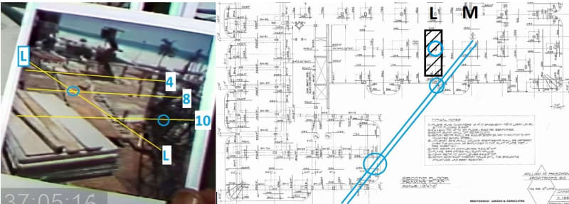
Watching the crane collapse video, it seems like this general planter area really was in the wars. The crane 'collapse' appears to have dropped the elevator wall formwork onto the deck, bending over the column starter bars on Grid L8.
The crane itself seems to have dropped down onto M10 where one can see the planter beam formwork (in other portions of the video). On the way down it also damaged the 2nd floor cantilever balcony at J14.
The west portion of the building appears to have been a floor or two ahead of the east. One wonders exactly where the pour joints were, possibly the podium deck was tied into columns J13, J14 and J15 later.

crane3_lxk0dt.jpg
 
Using numbers to allow focus on any particular part.
1) It certainly should address moments. However the graphic plan is titled "axial compression Loads" and that implies the moments may not have been addressed in this study.
2) Design for RC columns should address some minimum incidental moments, such as perhaps 5% of column dimension - perhaps 10%. As addressed prior, the shear walls are minimal at best and act in one direction only. The columns should have been designed for hurricane winds and that induces moments in the columns.
3) A lateral design with columns resisting shears from wind or seismic generally creates a point of inflection in columns that is at about the mid height between floors so shears in the column create (lets say) clockwise moments above the slab and likewise below the slab, and those additive moments have only a slab for resistance in this flat slab system.
4) The flat slab has column strips with reinforcing concentrated in those strips and which act as beams to support loads and moments. The cantilevered balconies provide negative moments at exterior columns to balance some of the loads from within the building. There are conditions where a c olumn exists at the edge of the floor area without a balcony, and the negative moments from the slab have only the columns for resistance. So the vertical load only can induce moments in the columns due to unbalanced floor loadings or locations, and the reinforcing must be detailed for development - and this can be difficult in thin slabs.
5) it appears this building is part non-sway frame and part sway-frame design As you stated correctly, in one direction it has some help from shear walls (not much tho) and in the other, the columns are all there is. And yes, the wind load design is additive and impacts the design of columns and slabs. Thus the beefed up reinforcing for the Second Floor slab due to the addition of the Penthouse.
If this happened in calm winds, think what the next hurricane could have done.
Thank you,
 

Thanks Vance Wiley, for answering my questions and explaining it very well. I realize it will take a detailed simulation to fully understand all the interactions of the individual components and the affects on the overall structural system, and connections. However, in my mind it seems this under nourished design allowed excessive movements of the structure, which it seems would just get worse with time and daily environmental load stress, live load changes, lack of proper maintenance and repair, etc.

It seems to me that the swaying from vibrations that was complained about by the association was the wake up call that something was really wrong, and had to be addressed immediately. I can't imagine even the least nerdy person not realizing something was bad wrong and letting it go unaddressed was just doing more damage every day.

Being a retired engineer, I know if my house was swaying from storm winds or whatever, I would be all over temporary bracing the structure ASAP, to prevent further damage cycles or collapse, until such time I devised a permanent solution. But then I am the owner, the bank, the engineer, and the skilled and unskilled laborer on my project home.... So there is no passing the buck option.

The house I am in now, had a deck racking problem when I bought it, which I easily solved with a diagonal lateral brace screwed to the bottom of the deck joists. I chose this approach because the upper deck was over a lower deck, and diagonal bracing would have blocked the view from the lower deck.

You would surely think the Association made Morabito aware of the sway issue, yet nothing in the certification plans seems to address that priority one issue? It also seems to me, Morabito should have done calculations based upon design drawings to determine loads, in order to be able to design repair solutions? It also would seem that a simple laser light level set up or a survey in the garage would have paid back in diamonds of value to evaluate the basement structure condition as far as deformations or variations in floor slab and beams. And that was very doable without kicking cars out of garage.
 
Quick question.
Does anyone know what concrete restoration work was being done in August of 2019?

Precision guess work based on information provided by those of questionable knowledge
 
All About Money (Aerospace)14 Aug 21 02:56 said:
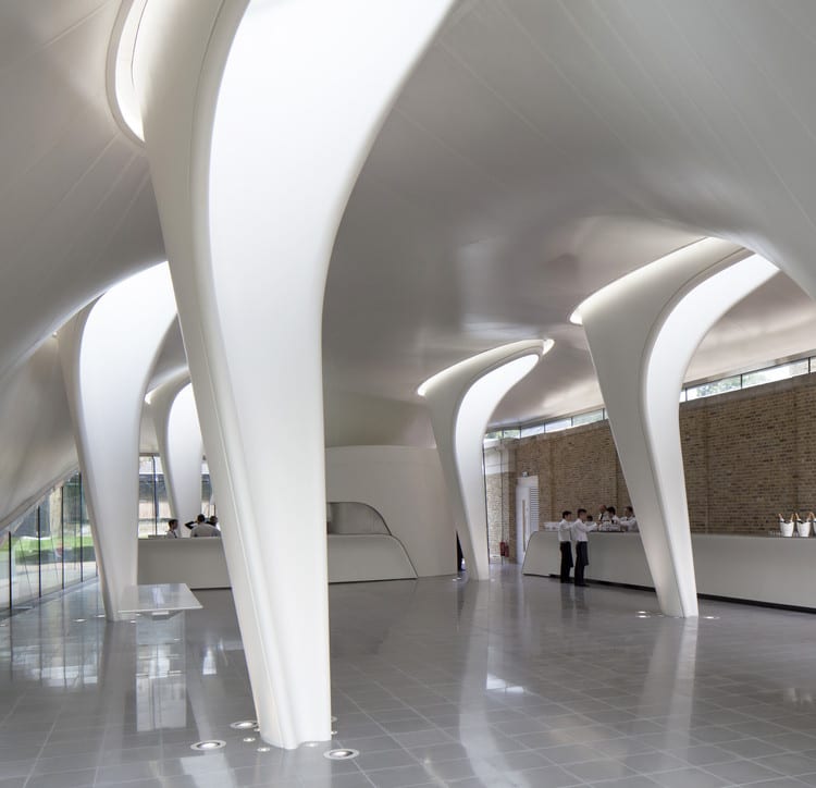
What would you call that 'Column' of Water in your image?
This is more my idea of a fluid column...
The_Serpentine_Sackler_Gallery_-_Zaha_Hadid_Architects_-_ArchDaily_ZHA_Serpentine_Sackler_Gallery_08_wdahiz.jpg

The Serpentine Sackler Gallery - Zaha Hadid Architects - ArchDaily
Thank you Zaha Hadid, may you rest in beauty and peace!


SF Charlie
Eng-Tips.com Forum Policies
 

Logical follow-on question is how do you design SFCharlie’s fluid/elastic columns in one direction, yet use a more rigid shear wall in the other direction/plane without some sort of flexible or adaptable isolation coupling in sway frame direction with shear wall? It seems the fluid movements in one direction would be constantly clashing with the braced direction.
 
All About Money (Aerospace)15 Aug 21 15:44 said:
Logical follow-on question is how do you design SFCharlie's
I don't think the columns are flexible, but if you would prefer something easier to calculate...
vitra-fire-station-zaha-hadid_901_CR_SP_018_apblqf.jpg

Spikey - AD Classics: Vitra Fire Station / Zaha Hadid
archdaily said:
Although Zaha Hadid began her remarkable architectural career in the late 1970s, it would not be until the 1990s that her work would lift out her drawings and paintings to be realized in physical form. The Vitra Fire Station, (1989)

SF Charlie
Eng-Tips.com Forum Policies
 
The 'fluid/elastic' columns are in London, worst seismic recorded is 3.9. When concrete goes fluid it has fractured and it is all over. Lots of confinement reinforcing is needed to keep the concrete inside the reinforcing cage.
As to how the building reacts, todays practice is something like lay out all lateral resisting elements, locate the center of rotation (CG) , and design for the direct load at whatever angle and add the rotational effects. Neglect any negative contributions if they reduce the direct load in a column or wall.
Lateral loads are estimated based on the seismicity of the site and building mass, and applied at the center of mass for each level. The load is applied at some minimum distance from the CG if that minimum exceeds the actual eccentricity. The minimum is a percentage of the building dimension in the direction being considered.
Today's seismic designs limit the amount of rotation allowed, with the effect of requiring designs with less rotation and more uniformity and/or symmetry in the lateral system.
In he case of CTS, the shear walls were a boundary for the immediate collapse. So lateral forces were not a great factor - it fell pretty straight down. However, for loads parallel to the shear walls, there would have been considerable eccentricity for the east wing, which collapsed. The floor slabs would have acted as cantilever diaphragms extending from the shear wall to the east, to provide N-S stability while the shear walls remained more or less intact.
The museum 'fluid/elastic' columns likely have different stiffness in each of the possible different directions and with rotation each column is loaded at a different direction.
That makes my head hurt and the accounting department goes nuts when they see how much time is required to design for all that.
Thanks,,
 
I realize the design of the fluid shape of those rigid columns would require ‘Cocaine Cowboys’ or Jeff Bezo Deep Pockets Level of Funding.


I am getting the impression the sway movements residents complained about were driven by column movements and perhaps long term deformations causing load redistributions. With the interior columns being heaviest loaded, it makes sense for the middle of initial collapse area to drop first perhaps and pull perimeter inward. Which makes you wonder if the building started the collapse?
 
There does not seem to be any report of something unusual - no seismic activity, no hurricane, no impact from large vehicles or airplanes, no Heavens opening and large lightening bolts - just another day in the life of a 40 year old building.
The graphic presentation with the "axial compression force ratio" information does suggest highly loaded columns in some areas and therefore lesser impacts could initiate failure. And the most highly loaded columns seem to be where the collapse started.
Starting with excessive demand/capacity ratios and overlaying 40 years of coastal environment exposure and inadequate maintenance leads us to today.
It will be interesting to see if the "axial compression force ratio"s withstand the coming analysis.
 
Vance Wiley said:
If the "axial compression force ratio" is correctly determined and presented it seems to mirrors the initial collapse quite well.

It can’t be correct as it’s using an incorrect and incomplete column schedule. Seems a bit misleading; more of a propaganda statement than an actual forensic analysis.
 
Status
Not open for further replies.

Part and Inventory Search

Sponsor