Continue to Site

Eng-Tips is the largest engineering community on the Internet

Intelligent Work Forums for Engineering Professionals

  • Congratulations KootK on being selected by the Eng-Tips community for having the most helpful posts in the forums last week. Way to Go!

Miami Pedestrian Bridge, Part I 65

Status
Not open for further replies.

JohnRBaker

Mechanical
Jun 1, 2006
35,556
Multiple Fatalities After Pedestrian Bridge Collapses Near Florida International University


As investigators continue to search the site of a deadly collapse involving a 950-ton pedestrian bridge near Florida International University in Miami Thursday, officials say the death toll has risen.

Early Friday morning, the Miami-Dade Police Department confirmed that six people have died as a result of the collapse....

John R. Baker, P.E. (ret)
EX-Product 'Evangelist'
Irvine, CA
Siemens PLM:
UG/NX Museum:

The secret of life is not finding someone to live with
It's finding someone you can't live without
 
Replies continue below

Recommended for you

I apologize if my style is offensive to some.
I don't apologize for the basic content of my post.
I have seen too many versions of that play out over the years.
Sometimes with injuries, often with property damage and sometime with firings.
Who is responsible?
Sometimes the engineer in his ivory office.
Sometimes the engineer on the ground personally directing the work, possibly against the advice of experienced tradesmen.
Sometimes the crew is taking a shortcut.
Sometimes the crew does not follow directions.
Sometimes the crew does not understand the instructions.
Sometimes people get fired.
Sometimes the right people get fired but not always.
Sometimes the accident report is accurate and true.
Sometimes not.
And sometimes shtuff happens.
Why are cameras banned on many construction sites?
There is nothing like a photograph to screw up a perfectly good coverup.

Extraneous thought: After the Columbia bridge failure and now this one;
Maybe all cracks in important structure should be treated as serious until proven otherwise.
Inconvenient in many cases yes.
How much inconvenience is more important than a fatality?

Design/build?
Sometimes it works, but most of the old timers here have seen the results of profit driven decisions made on design build projects.
One that comes to mind is a pulp mill that was profitable for over twenty years.
Then came the design/build expansion and a newsprint mill was added.
There is nothing like improperly driven foundation pilings to mess up a newsprint drier.
In a few short years the company was out of business and the entire mill was dismantled and shipped to the third world.
The design/build company is still in business.


Bill
--------------------
"Why not the best?"
Jimmy Carter
 
waross... you sure you're not a structural guy?

Just curious...

Dik
 
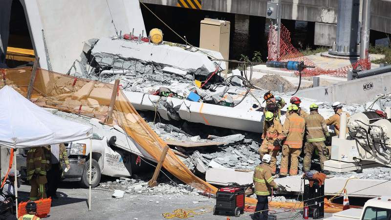
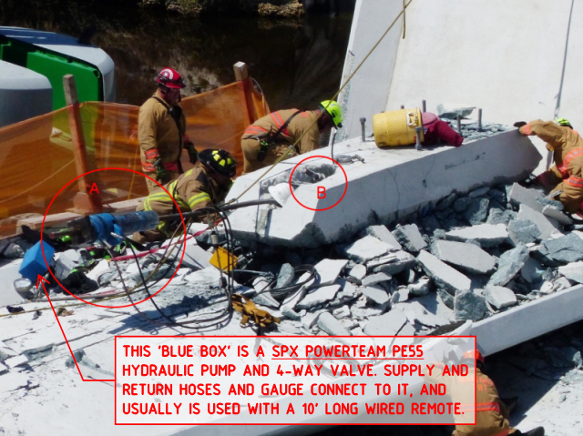
gte447f - I have been skeptical of witness statements as well because they are often unreliable. There are actually 3 blue objects. The ram, the metering/pressure rig (control box) and the hydraulic fluid reservoir. With the arched canopy, the thought to sling the control box from the crane might have seemed like a good idea at the time. If indeed, this was the case, then the investigators probably already know that, when the control box fell and uncontrolled pressure surge to the jacking ram overloaded the tendon. Full Size Photo: Link

Ram_Hydraulic_resrv._xpertb.jpg
 
miami_6_sbtu1e.png


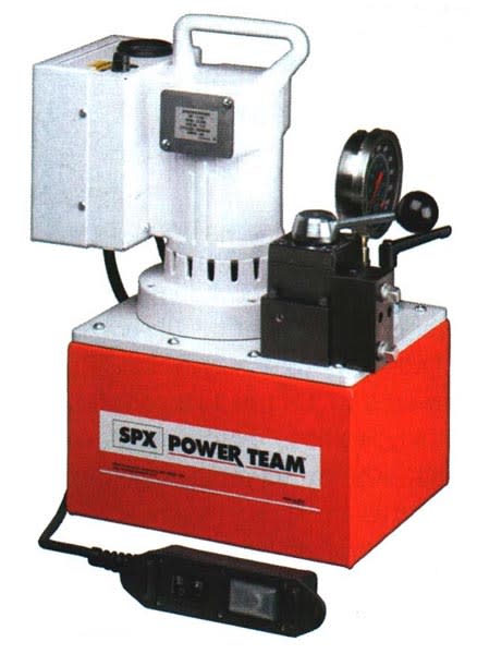
Original 'Powerteam' orange that was re-painted in VSL 'blue':

MIAMI_5_mvpbkz.jpg


Full of oil, these pumps weight about 65 lb.

Stressing is always a two-person (minimum) operation: pump operator and jack 'stressor'. If you look at the videos that Tomfh and epoxybot post you can see a guy fall as his lanyard tie-off breaks, so likely that the pump and operator were in a 'dog box' suspended from the crane.
 
If the "pipe stays" were indeed almost cosmetic, then it bothers me a lot that all of the diagonals of the truss were aligned with the stays, instead of given simpler geometry.
 
epoxybot said:
...metering/pressure rig (control box) and the hydraulic fluid reservoir.

I cannot see a 'third blue object'. And with a PE55 pump the 4-way control valve (for double-acting ram) and oil reservoir are all contained within the same box, as my photo above shows (the orange pump).
 
AggieYank said:
If the "pipe stays" were indeed almost cosmetic, then it bothers me a lot that all of the diagonals of the truss were aligned with the stays, instead of given simpler geometry.

Don't let some engineering get in the way of some bridge 'art'. It is in PINK for sarcasm!
 
Given the end result, where people lost their life, this is an inexcusable and unacceptable result.

Having said that, something to consider: If you have never worked for a contractor or on a project where you are responsible for project execution, then consider that something that appears black and white from the design office "ivory tower", is quite a bit grey-er in the field.
 

I agree, but the whole situation is still puzzling. Was the span designed as a truss or as an "I" section with web cutouts? If we assume it was designed as a determinant truss, Members 2 and 11 would have been in tension while the bridge was moved into place, based upon the position of the SPMT's in the photos, thereby requiring PT. Also,the deck or bottom chord of the first and last panels would have gone suddenly from compression to tension once the SPMT jacks were lowered. Perhaps in the final position, Member 11 had too much compression, which resulted in the "de-tensioning" operation.

IMHO, if it were designed as a truss it was the wrong approach. Forgive me if I'm rambling.
 
With regards to discussions about tensile failure of the PT bar, the stressing levels to PT bars were significant on some of the members, especially member #10.

The PT bar appears to be Williams Grade 150 ksi: Link.

For the 175' span truss, member #10 had its 4 PT bars stressed to 280 kips each. Min. UTS is 390 kips, so max was 72% of ultimate tensile. PTI (and manufacturer's) recommendations stipulate max of 80% of MUTS for test loads (usually for rock or soil anchor type projects where proof testing is undertaken), but there is also a requirement that the lock-off load should not exceed 70% of the specified minimum tensile strength. Threaded PT bar does not undergo significant seating losses like strand/wedge systems, so the stressing load is the lock-off load, for all intents-and-purposes.

The other PTI requirement is that the design load is not more than 60% of the specified minimum tensile strength of the prestressing steel.

The other PT bars to members of the 175' truss were stressed to 52% and 62% of MUTS.

I have not seen photos to show evidence of a tensile failure of the PT bar. The 10 foot 'projection' of the PT bar and jack from the canopy 'blister' could be explained by 'nodal' failure at the bottom of member #11 diagonal, where the bottom chord appears to have ripped away from the support 'node'.

 
What I see in the two photos are a Blue ram & control box with what looks like a blue plastic reservoir (with rounded corners) and then in the other picture a scratched blue metal ?reservoir?. Perhaps in the photo with the A & B designations the reason the third item cant be seen is because it is behind the fireman. IDK.
 
All the photos show me that the failure was a joint failure rather that a member failure. Both ends of Member 10 developed hinges at the same time. We have focused on PT in the members, but have no knowledge of bonded mild steel reinforcement in the structure, or of the joint reinforcement.

Just wondering...of all the engineers here, has anyone ever designed or had knowledge of a concrete truss?

Bridgebuster, you have it right, a truss made of concrete was the wrong approach.
 
NOTICE:

This thread is getting long. Discussion continued in new thread:

thread815-436699
 
Status
Not open for further replies.

Part and Inventory Search

Sponsor